Electrical ratings:
XLD-1 Input
24V unfiltered,
full wave rectified
(Alarm and Supervisory),
215mA at 24 VDC (no devices)
1.1mA at 24 VDC (per device)
Initiating Circuits
28 VDC peak
(Alarm and Supervisory),
40mA max per circuit
(0-30 devices in alarm)
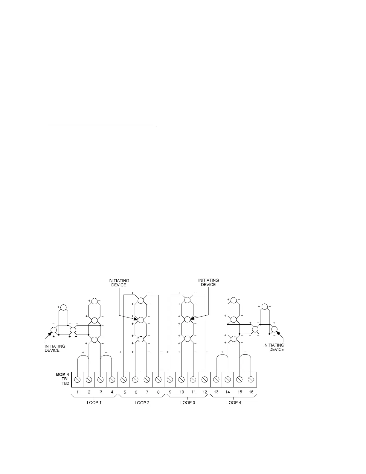
XLD-1 Connections and Ratings
4 - 113
XLD-1 Wiring
Battery Calculations
XLD-1 Module Current: 215mA
Device Current: 1.1mA per device
All wiring must be in accordance with
Article 760 of NEC and the local
building codes.
NOTES
1. Power limited to
NFPA 70 per NEC 760.
2. Minimum wire size:
18 AWG.
3. Maximum resistance:
100 ohms total.
4. Maximum
capacitance:
0.4µF between
+ loop and loop.
0.8µF between
+ loop and chassis.
0.8µF between
loop and chassis.
5. Each detector or
group of detectors,
requires a two-wire
circuit of thermo-
plastic fixture wire
enclosed in conduit
or limited energy
shielded cable
without conduit, if
permitted by local
building codes.
6. No end of line device
required.
7. Operates in full
conformance with
Style 6.
8. Operates in full
conformance with
Style 4.
9. Any loop may be
wired Class A or B.
10. 30 devices maximum
per loop.
11. T-tapping is NOT
allowed on Class A
loops.
12. All circuits are
supervised.
ANY LOOP MAY BE WIRED AS CLASS A OR CLASS B
NO END OF LINE DEVICE REQUIRED
ALL CIRCUITS SUPERVISED AND POWER LIMITED PER NEC 760
CLASS B WIRING
See Note 8
T-TAPPING ALLOWED
CLASS B WIRING
See Note 8
T-TAPPING ALLOWED
CLASS A WIRING
See Note 7
NO T-TAPPING ALLOWED
Technical Manuals Online! - http://www.tech-man.com

 Loading...


