2 - 32
Installation
ASC-1 S1 SETTINGS
Amplifier 1 uses S1, switches SW1 and SW2
SW2 SW1 Amplifier Input
OO Riser 1
OX Riser 2
XO Riser 3
X X No amplifier connected
Amplifier 2 uses S1, switches SW3 and SW4
SW4 SW3 Amplifier Input
OO Riser 1
OX Riser 2
XO Riser 3
X X No amplifier connected
Amplifier 3 uses S1, switches SW5 and SW6
SW6 SW5 Amplifier Input
OO Riser 1
OX Riser 2
XO Riser 3
X X No amplifier connected
X=Closed or ON O=Open or OFF
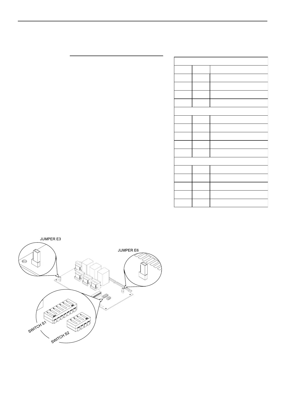
Switches S1 and S2 and Jumpers E3 and E6 on the ASC-1
Installing the ASC-1
The ASC-1 plugs into a half-width slot
on the OMM and comes with an
installation kit that consists of the
following:
One user key
Setting the Addresses on the ASC-1
Before installing the ASC-1 in the
OMM, set S1 and S2. Use S2, DIP
switches SW1-SW4 to set the network
address. Refer to the CSG-M configura-
tion printout for the address of the
module. Use the ASC-1 S2 Settings
table to set the address for this switch.
Set switch S1 for proper amplifier
supervision of the ASC-1. Check the
system wiring diagram for amplifier
and riser assignments. Set switch S1
DIP switches SW1 - SW6 using the
ASC-1 S1 Settings table.
If this ASC-1 card supervises the
backup amplifier, SW7 on switch S1
must be CLOSED or ON. If one backup
amplifier is shared by more than one
ASC-1 card, SW7 of S1 must be OPEN
or OFF on all ASC-1 cards except the
one supervising the backup amplifier.
Setting Jumper E3
Jumper E3 sets the ASC-1 for 25.2V
RMS or 70.7V RMS amplifier output.
To set the jumper for 25.2V RMS,
place the E3 jumper in the left-hand
position (gold-plated edge facing as
shown).
To set the jumper for 70.7V RMS,
place the E3 jumper in the right-hand
position (gold-plated edge facing as
shown).
Technical Manuals Online! - http://www.tech-man.com

 Loading...


