2 - 29
Installation
the REP-1 has two positions relating to
this featurePSR and MMB.
Select the left-side position (PSR)
for the jumper if the REP-1 is in-
stalled in an enclosure with a PSR-1.
This setting provides ground fault
isolation for the system.
Select the right-side position (MMB)
for the jumper if the REP-1 is in-
stalled in an enclosure with an
MMB-1/-2 so as to provide ground
fault detection.
Checking Limits
Do not connect more than two REP-1s
in series for proper operation of the
network. To be sure there are no
more than two REP-1s in series,
check that:
There are no more than two
REP-1s between any MXL module
and the MMB-1/-2,
or
In an NIM-1R network, there are no
more than two REP-1s between any
pair of NIM-1Rs in the network.
Installing the NET-7 into the MOM
Decide whether to install the NET-7 in
a PSR-1 (refer to page 2-6) or in the
enclosure with the MMB-1/-2. The
NET-7 module plugs into one half-
width slot on the MOM.
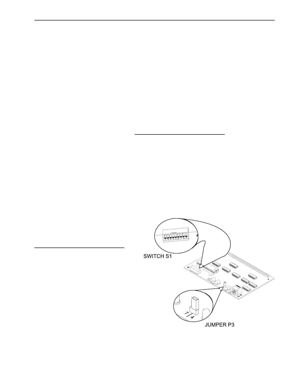
Setting the Address on the NET-7
Set the network address for the
NET-7 using switch S1. Use the
Network Address Programming Table
at the end of this chapter to set the
address for this switch. Be sure that
the address agrees with the CSG-M
network map.
Determine whether the communica-
tion mode is Style 4 or Style 7. Place
the shorting jumper on P3 to agree
with the style selected.
After setting the address and jumper,
install the NET-7 in the MOM, being
sure that the module is riding in the
card guides and is firmly seated in the
card edge connector.
Installing the NET-7M into the MOM
Decide whether to install the NET-7M
in a PSR-1 (refer to page 2-7) or in the
enclosure with the MMB-1/-2. The
NET-7M module plugs into one half-
width slot on the MOM.
Install the NET-7M in the MOM, being
sure that the module is riding in the
card guides and is firmly seated in the
card edge connector.
Switch S1 and Jumper P3 on the NET-7
Technical Manuals Online! - http://www.tech-man.com

 Loading...


