Electrical ratings:
24 VDC input 14-31 VDC
300mA max
5 VDC output 5 VDC
500mA max
Network 8V P-P max
150mA max
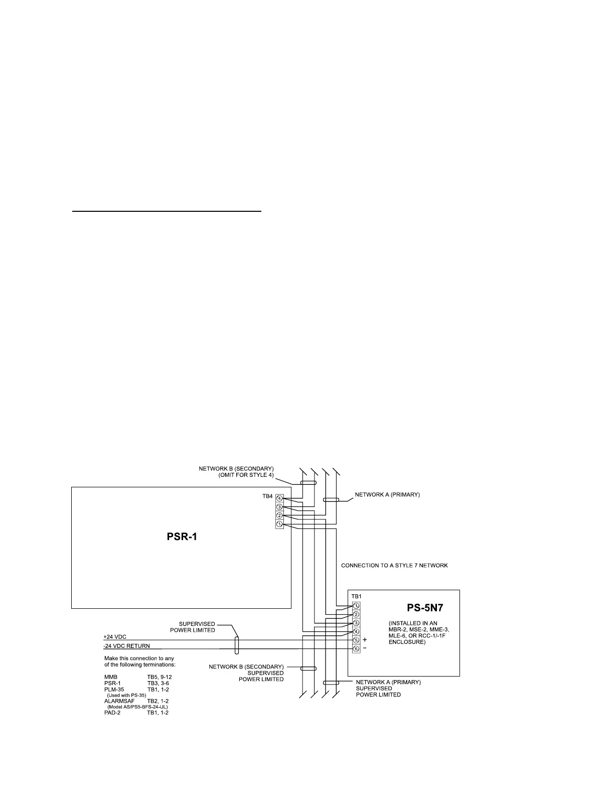
The PS-5N7 requires a DC input which
is available from the MMB-1/-2 or the
PSR-1.
PS-5N7 Connections and Ratings
4 - 75
PS-5N7 Power Supply and Network Wiring
Using the PS-5N7 with Style 4 (2-Wire)
Network Connections
Use screw terminals 1 and 2 for Net-
work A. DO NOT USE wire terminals 3
and 4 in this configuration. Refer to the
PSR-1 Installation Instructions (P/N
315-090911) for more details on Style
4 networks.
Using PS-5N7 with Style 7 (4-Wire)
Network Connections
Do not place the PS-5N7 module in the
last position on a Style 7 Network. Use a
NET-7 at each end of the network to
provide proper supervision. Use screw
terminals 1 and 2 for Network A, termi-
nals 3 and 4 for Network B.
NOTES
1. Power limited to
NFPA 70 per NEC 760.
2. Minimum wire size:
18 AWG.
3. Maximum resistance:
80 ohms per pair.
4. Use twisted pair or
shielded twisted pair.
5. Terminate the shield
ONLY at the MMB-1/-2
enclosure.
6. Maximum voltage:
8V P-P.
7. Maximum current:
150mA.
8. Eliminate all Network
B wiring for Style 4.
9. DO NOT place the
PS-5N7 at the end of
the network (Style 7
only).
Refer to the following
Installation Instructions
for further information:
MMB-2 P/N 315-095097
PSR-1 P/N 315-090911
PS-35 P/N 315-085062
PLM-35 P/N 315-093495
PAD-2 P/N 315-094275
Technical Manuals Online! - http://www.tech-man.com

 Loading...


