2 - 41
Installation
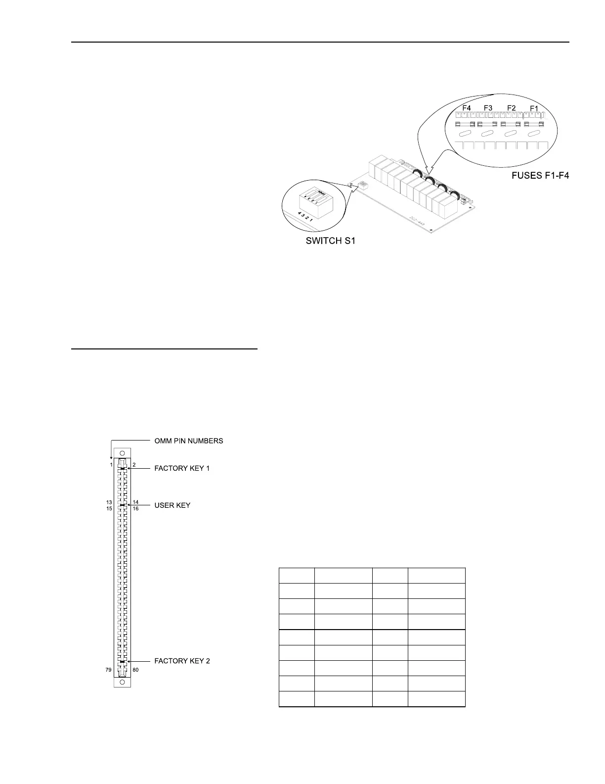
For 25.2V Installations, remove the
70V fuses, F1-F4, and install the 25V
fuses, P/N 105-291200, found in the
installation kit.
Place the user key from the installation
kit in the OMM-1 card edge connector
for the ZC2-4AB (between positions
13-14 and 15-16).
After the address is set, install the
ZC2-4AB in the OMM, being sure that
the module is riding in the card guides
and is firmly seated in the card edge
connector.
Installing the ZC3-4AB
The ZC3-4AB plugs into a half-width
slot on the OMM and comes with an
Switch S1 and Fuses F1-F4 on the ZC2-4AB
Location of the User Key for the ZC2-4AB
installation kit that consists of the
following:
Four end of line resistors,
P/N 140-820405
One 2A, 250V fuse, P/N 105-292199
Four 25V fuses, P/N 105-291200
One user key
Setting the Address on the ZC3-4AB
Before installing the ZC3-4AB in the
OMM, set the address on S1, DIP
switches SW1-SW4. Refer to the
CSG-M configuration printout for the
address of the module. Use the
ZC3-4AB S1 Settings table to set the
address for this switch.
ZC3-4AB S1 SETTINGS
Address 4 3 2 1 Address 4 3 2 1
ILLEGAL O O O O 008 X O O O
001 O O O X 009 X O O X
002 O O X O 010 X O X O
003 O O X X 011 X O X X
004 O X O O ILLEGAL X X O O
005 O X O X ILLEGAL X X O X
006 O X X O ILLEGAL X X X O
007 O X X X ILLEGAL X X X X
X=Closed or ON O=Open or OFF
ZC3-4AB S1 SETTINGS
Technical Manuals Online! - http://www.tech-man.com

 Loading...


