2 - 13
Installation
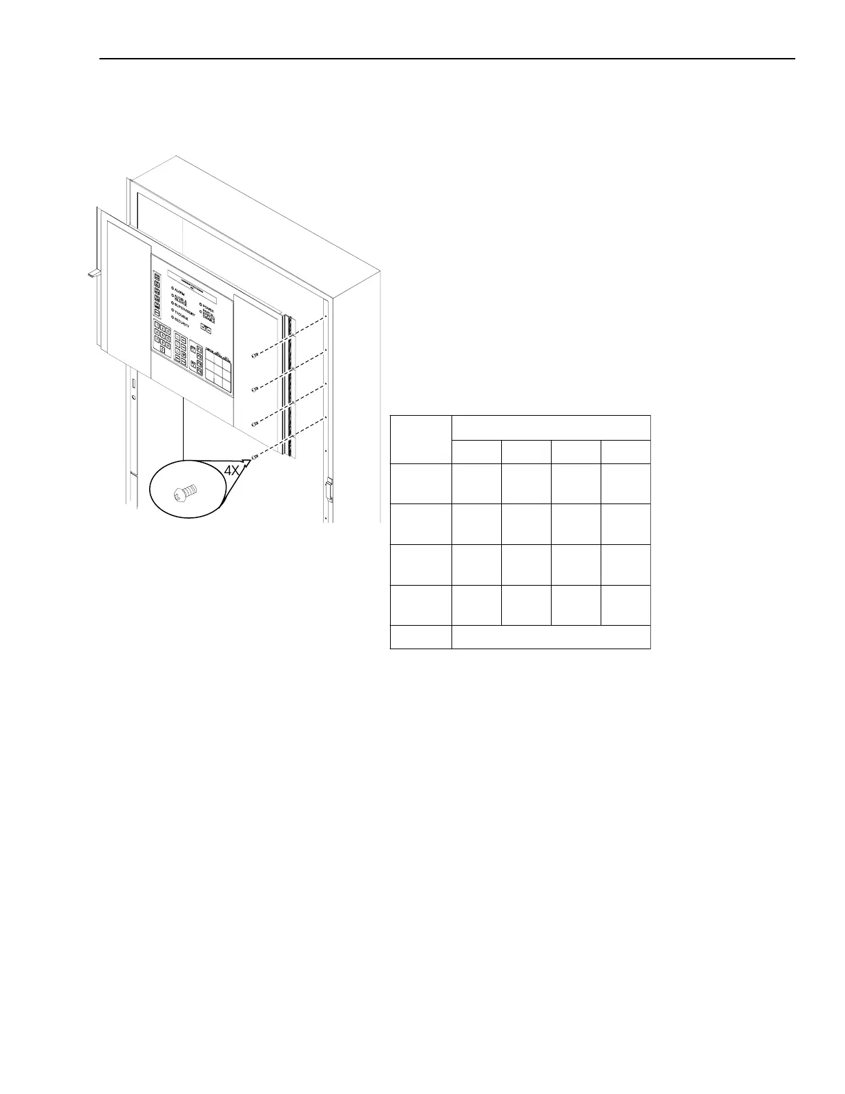
If the panel locking fastener is not
aligned with the hole located on the
left flange, loosen the screws and
adjust accordingly. Retighten the
screws.
Once the MKB-2 is mounted to the
enclosure, connect the cable (P/N 555-
192238) between P1 on the ANN-1 (on
the back of the MKB-2) and P8 on the
MMB-1/-2.
NOTE: Remember that this cable is
polarized and connects in one way only.
Do not force it. Be sure the black tracer
wire on the edge of the cable is close
to the 1 on position 1 of the connec-
tor P1 on the ANN-1 and the 1 on
position 1 or P8 on the MMB-1/-2.
Setting the ANN-1 Network Address
Set the network address on S1, the
switch on the ANN-1 board located
on the back of the MKB-2. Use DIP
switches SW1 and SW2 on switch
S1 to set the network address of
the MKB-2.
The MKB-2 module address is
always set within network addresses
248 - 251. Set the individual switches
as follows:
ANN-1 SWITCH SETTINGS
Switch
Address Setting For:
248 249 250 251
S1-SW1
Open-
OFF
Closed-
ON
Open-
OFF
Closed-
ON
S1-SW2
Open-
OFF
Open-
OFF
Closed-
ON
Closed-
ON
S1-SW3
Closed-
ON
Closed-
ON
Closed-
ON
Closed-
ON
S1-SW4
Closed-
ON
Closed-
ON
Closed-
ON
Closed-
ON
S1-SW5 See Setting Supervision
One supervised MKB-2 must be
installed at network address 251.
Other supervised MKB-2s may be
at the other addresses.
Setting Supervision
Use switch S1-SW5 on the ANN-1 to
select or deselect supervision. If your
ANN-1 has a switch with position 1
indicated on the left-hand side, ignore
the printing on the switch. SW1 on S1
is at the extreme right-hand side of S1,
regardless of any other marking.
Mounting the MKB-2
Technical Manuals Online! - http://www.tech-man.com

 Loading...


