2 Installation and Commissioning, IRC5
2.9.7. Installation of Euromap and SPI
3HAC021313-001 Revision: K130
© Copyright 2004-2008 ABB. All rights reserved.
Installation of the cable and converter box (Euromap 12)
The following procedure details how to install cable between the controller and the injection
moulding machines.
WARNING!
To run the robot for commissioning without injection moulding machine, you have to jumper
the safety channel from the robot and spend 24V for the safety device relays (for Euromap
12). Use the included jumper plug (Harting connector).
12. Connect the connectors X1, X2, X3 and X4 on
I/O 2.
See the location of I/O 2 in Location of
Euromap harness in the Dual Cabinet
on page 124.
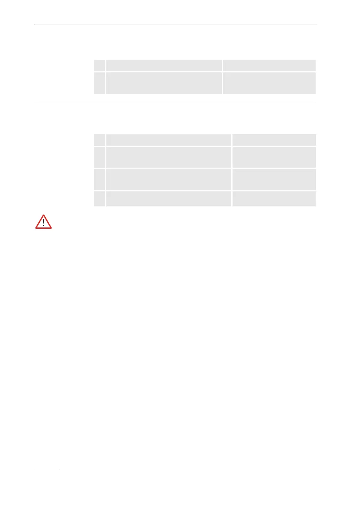
Action Note/Illustration
Action Note/Illustration
1. Connect the cable between converter box and the
controller.
See Required equipment for
Euromap 12 and SPI (Option no.
671-1) on page 125.
2. Connect the cable between the injection moulding
machine and the converter box.
See Required equipment for
Euromap 67 (Option no. 671-2) on
page 124.
3. Connect a 0V wire between the internal IMM power
supply and pin 31 in the IMM connector.
See
Continued
 Loading...


