2 Installation and Commissioning, IRC5
2.6.2. Configuration of the drive system, IRC5
3HAC021313-001 Revision: K94
© Copyright 2004-2008 ABB. All rights reserved.
IRB 6600, 7600
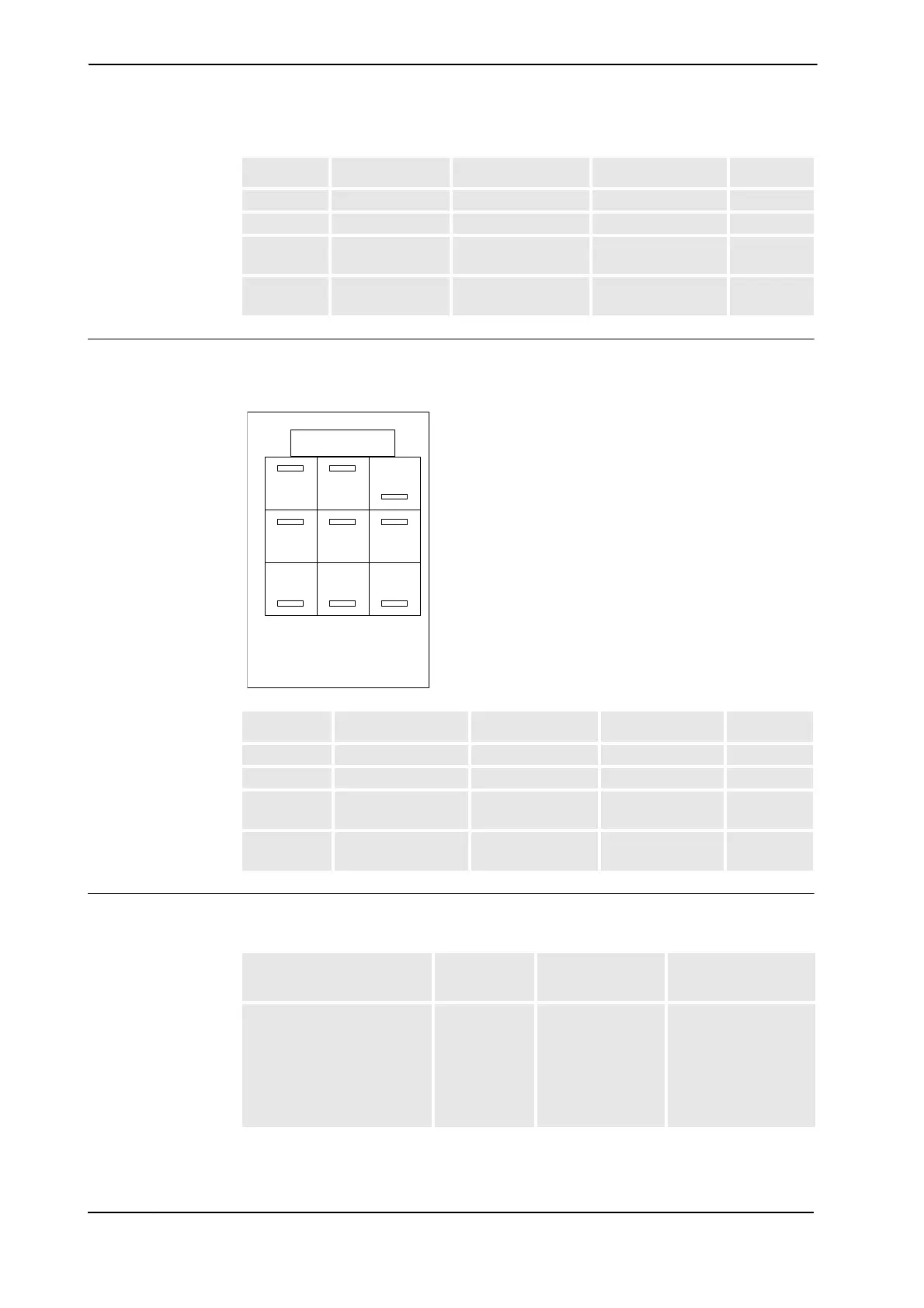
The figures show the drive unit with and without additional axes respectively. The table
specifies which units may be fitted in which positions.
xx0300000184
Drive unit connection
The table below shows the drive unit connection for each drive unit.
Pos. Identification Description Art. no. Note
1 DSQC 620_C4 Capacitor unit 3HAC14551-3
Z2 DSQC 618_R2 Rectifier 3HAC14549-2
Y2, X2 DSQC 619 Optional drive units
for external axes
3HAC14550-4 Size: 1W
Z4, Y4, X4,
Z3, Y3, X3
DSQC
617_3V3W
Main Drive unit 3HAC025338-006 Z4 - X3 is
ONE unit!
Pos. Identification Description Art. no. Note
1 DSQC 620_C3 Capacitor unit 3HAC14551-2
Z2 DSQC 618_R3 Rectifier 3HAC14549-3
Y2, X2 DSQC 619 Optional drive units
for external axes
3HAC14550-4 Size: 1W
Z4, Y4, X4,
Z3, Y3, X3
DSQC 617_3V3W Main Drive unit 3HAC025338-006 Z4 - X3 is
ONE unit!
1
2
3
4
Z
Y
X
Rectifier: Z2
Capacitor: 1
Main drive unit: Z4 - X3
Single drive unit: 7=Y2/8=X2
Main drive unit Power stage
Designation in
circuit diagram
Template file name
(drive unit name)
DSQC 617_3B3A
Used for irb 140
•B
•B
•A
•A
•B
•A
M1 (R,S,T)
b
M2 (R,S,T)
M3 (R,S,T)
M4 (R,S,T)
M5 (R,S,T)
M6 (R,S,T)
M1 (DMX)
c
M2 (DMX)
M3 (DMX)
M4 (DMX)
M5 (DMX)
M6 (DMX)
Continued
Continues on next page
 Loading...


