Prepared by, date:
71
We reserve all rights in this document and in the information contained therein.Reproduction, use or
disclosure to third parties without express authority is strictly forbidden. © Copyright 2003 ABB
Page 70
153Total
3HAC024480-004
Latest revision:
Approved by, date:
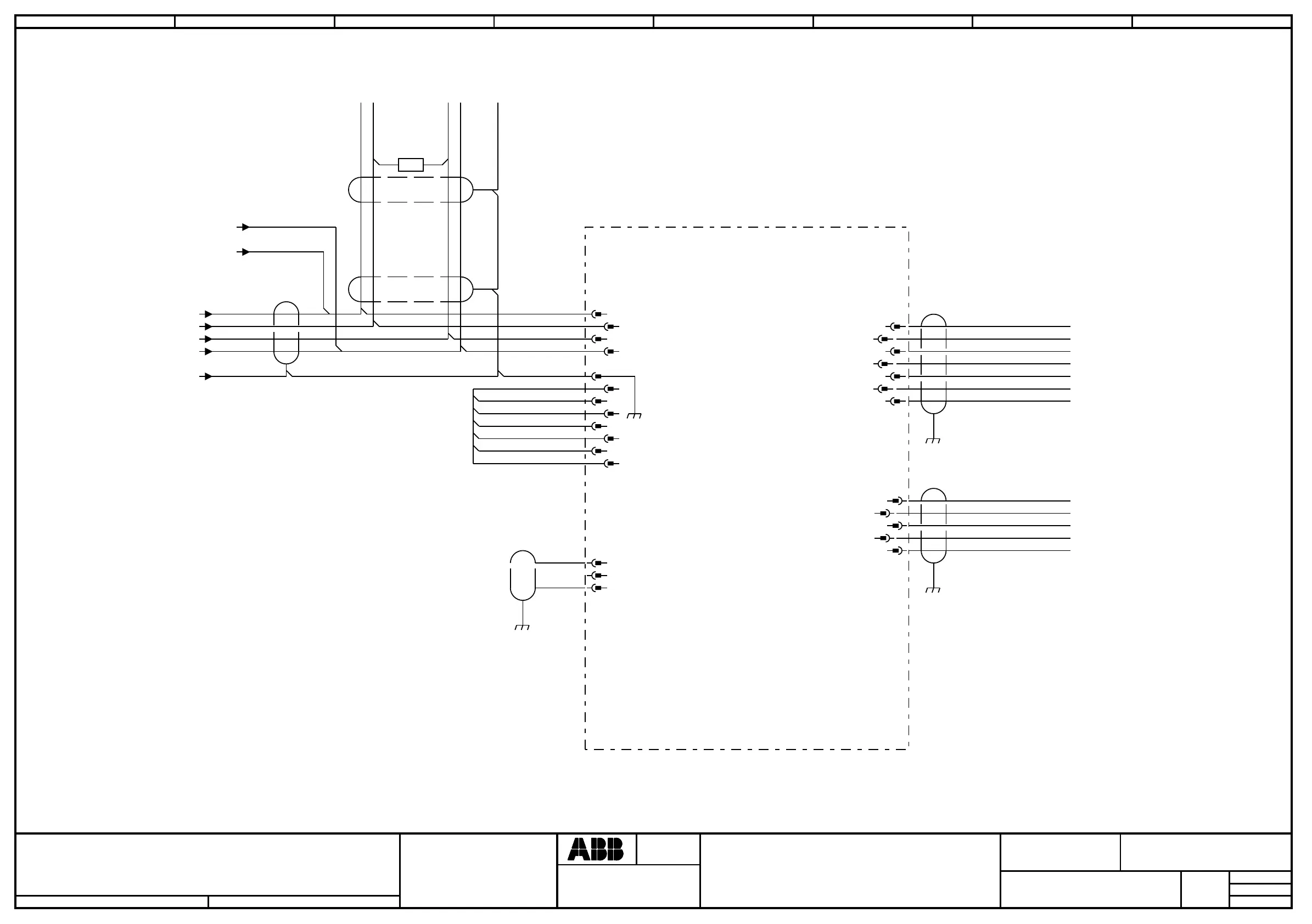
INTERBUS SLAVE
Location:
Plant:
=
+
+
Sublocation:
CAB
CM
SLO.5
Document no.
Next
Rev. Ind
03
Lab/Office:
Status:
CONTROL SYS. IRC5 M2004 DESIGN 06
Approved
2008-07-17
1 2 3 4 5 6 7 8
1) JUMPERS PLACED ACCORDING TO
THE ACTUAL NODE ADDRESS.
2) RESISTANS 120 OHM SHALL ALWAYS
BE CONNECTED IN THE FIRST AND THE
LAST CONNECTOR IN THE CAN-BUS CIRCUIT.
3) CONNECTED IN THE LAST CONNECTOR IN THE
CAN-BUS CIRCUIT.
4) IT IS IMPORTANT THAT 24V DC EXT SUPPLY
ALWAYS IS AVAILABLE. OTHERWISE THE
INTERBUS CAN NOT WORK IF THE CONTROLLER
IS TURNED OFF.
OR PREVIOUS
I/O UNIT
/60.5 / V-
/60.5 / CAN_L
/60.5 / CAN_H
/60.5 / V+
/60.5 / DRAIN
3)
120 ohm
12
2)
4) 24V DC EXT. SUPPLY
TO NEXT
I/O UNIT
GND
+24VDC
1)
0V
NA0
NA1
NA2
NA3
NA4
NA5
-X5
1
1
4
4
3
3
7
7
9
9
11
11
-X3
1
1
3
3
5
5
2
2
5
5
6
6
8
8
10
10
12
12
22
66
2
2
5
5
7
7
-X20
11
33
77
-X21
1
1
3
3
6
6
9
9
TPDO2
TPDI2
GND
+5VDC
TPDO2-N
TPDI2-N
RBST
TPDO1
TPDI1
GND
TPDO1-N
TPDI1-N
IB-S OUT
IB-S IN
-I/Ox
INTERBUS SLAVE
/35.7 /37.5 /34.4 /36.7 / +24Vdevicenet;6
/35.7 /37.5 /34.4 /36.7 / 0Vdevicenet;6
 Loading...


