4 Repair activities, controller IRC5
4.6. Replacement of backup energy bank
2113HAC021313-001 Revision: K
© Copyright 2004-2008 ABB. All rights reserved.
4.6. Replacement of backup energy bank
Location
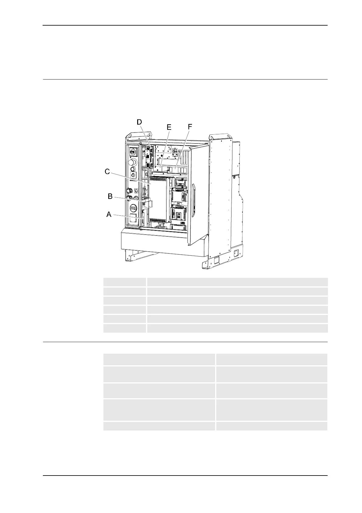
The illustration below shows the location of the backup energy bank in a Single Cabinet
Controller.
In the Dual Cabinet Controller the backup energy bank is located in the Drive Module.
xx0500001951
Required equipment
A Contactor interface board
B Contactor
C Drive system power supply
D Customer I/O power supply
E Control power supply
F Backup energy bank
Equipment Note
Backup energy bank DSQC 655 with or without adapter plate.
See Controller system parts on page 321.
Standard toolkit The contents are defined in section Standard
toolkit!
Other tools and procedures may be required.
See references to these procedures in the
step-by-step instructions below.
These procedures include references to the
tools required.
Circuit Diagram See Circuit Diagram on page 341.
Continues on next page
 Loading...


