4 Repair activities, controller IRC5
4.8. Replacement of heat exchange unit and fan
3HAC021313-001 Revision: K218
© Copyright 2004-2008 ABB. All rights reserved.
4.8. Replacement of heat exchange unit and fan
Location
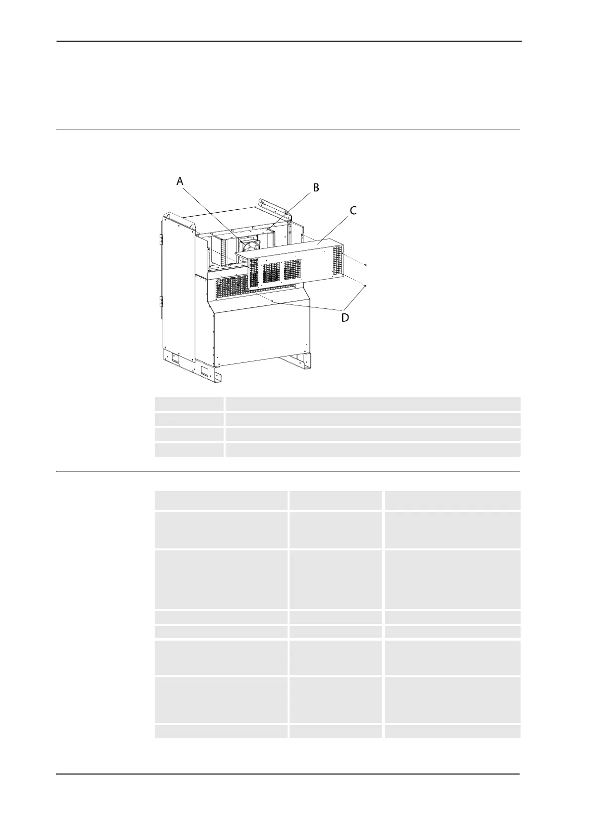
The heat exchanger unit is located in the back of the Control Module as shown below. On the
Dual Cabinet Controller the heat exchange unit is located on the Control Module.
xx0500001952
Required equipment
A Fan
B Heat exchanger
C Top cover
D Attachment screws (4 pcs)
Equipment Spare part no. Note
Fan with receptacle 3HAC021700-001 Room temp MAX52°C
IRB 6600, IRB 7600 IRB 660 and
IRB 6620
Fan with receptacle 3HAC021702-001 Room temp (MAX45°C) or Room
temp (MAX52°C)
IRB 140, IRB 340 IRB 1400,
IRB 2400, IRB 4400 and
IRB 1600
Heat exchange unit 3HAC024439-001 Room temp MAX52°C
Adhesive Product name, Casco S55
Standard toolkit The contents are defined in
section Standard toolkit, IRC5 on
page 317.
Other tools and procedures may
be required. See references to
these procedures in the step-by-
step instructions below.
These procedures include
references to the tools required.
Circuit Diagram See Circuit Diagram on page 341.
Continues on next page
 Loading...


