2 Installation and Commissioning, IRC5
2.5.10. The MOTORS ON/MOTORS OFF circuit
3HAC021313-001 Revision: K68
© Copyright 2004-2008 ABB. All rights reserved.
2.5.10. The MOTORS ON/MOTORS OFF circuit
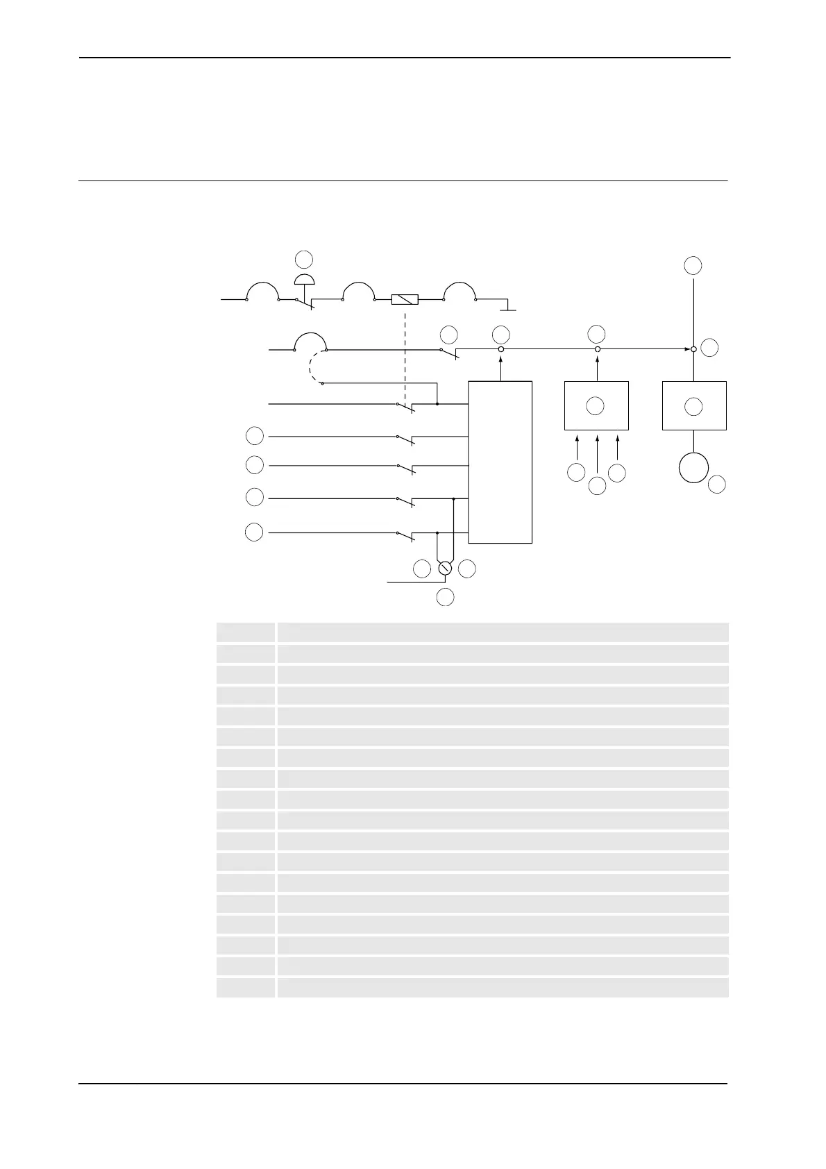
Outline diagram
The MOTORS ON/MOTORS OFF circuit is made up of two identical chains of switches.
The diagram shows the available customer connections, AS, GS, SS and ES.
xx0100000174
A ES (emergency stop)
B LS (Limit switch)
C Solid state switches
D Contactor
E Mains
F Drive unit
G Second chain interlock
H GS (general mode safeguarded space stop)
J SS (superior stop, same function as GS)
K AS (Automatic mode safeguarded space stop)
L ED (TPU enabling device)
M Manual mode
N Automatic mode
O Operating mode selector
P RUN
R EN1
S EN2
T Motor
A
&
N
O
P
R
D
E
F
G
M
H
C
C
B
J
K
L
S
T
Continues on next page
 Loading...


