54-3
Catalyst 6500 Series Switch Software Configuration Guide—Release 8.7
OL-8978-04
Chapter 54 Configuring ASLB
Understanding How ASLB Works
The LocalDirector supports directed mode and dispatched mode. Only the dispatched mode can be
supported for ASLB feature implementation on Catalyst 6500 series switches.
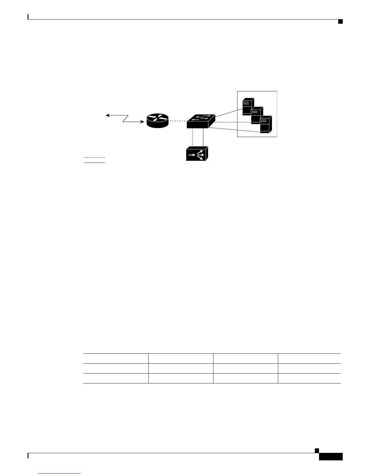
Figure 54-1 ASLB Functional Description
Layer 3 Operations for ASLB
You can specify up to 1024 server virtual-IP addresses and TCP port pairs for acceleration by the switch.
All the traffic for the virtual-IP/port pairs specified is accelerated except for the SYN, FIN, RST, and
fragment packets with a nonzero offset. These packets are redirected to both the active and standby
LocalDirectors (if a backup LocalDirector is configured).
Layer 2 Operations for ASLB
The Catalyst 6500 series switch content-addressable memory (CAM) table contains entries for the router
VLAN and the server VLAN. In the CAM table, the router VLAN has an entry for the MAC address of
the LocalDirector that is associated with a port index, and the server VLAN has entries for the router
MAC addresses that are associated with the port indexes. In these port indexes, the ports appear as 0/0.
You can display system CAM entries by entering the show cam system command.
Table 54-1 shows the entries in the CAM table (the ASLB configuration is shown in Figure 54-1). The
first entry identifies the MAC address of the LocalDirector on VLAN 10. The CAM table shows that the
MAC address has an Xtag value of 14. This value indicates that the MAC address requires a Layer 3
lookup. The second entry identifies the MAC address of the router and also requires a Layer 3 lookup.
Table 54-1 Layer 2 Table Entries
VLAN MAC Address Index Xtag
1
1. Xtag = The identifier field in the Layer 2 table that identifies the router to which the MAC address belongs.
10 LocalDirector MAC 0/0 14
20 Router MAC
2
2. Note that the router MAC address is added on the server VLAN (VLAN 20), not on the router VLAN (VLAN 10).
0/0 14
 Loading...