54-6
Catalyst 6500 Series Switch Software Configuration Guide—Release 8.7
OL-8978-04
Chapter 54 Configuring ASLB
Understanding How ASLB Works
Server-to-Client Data Forwarding
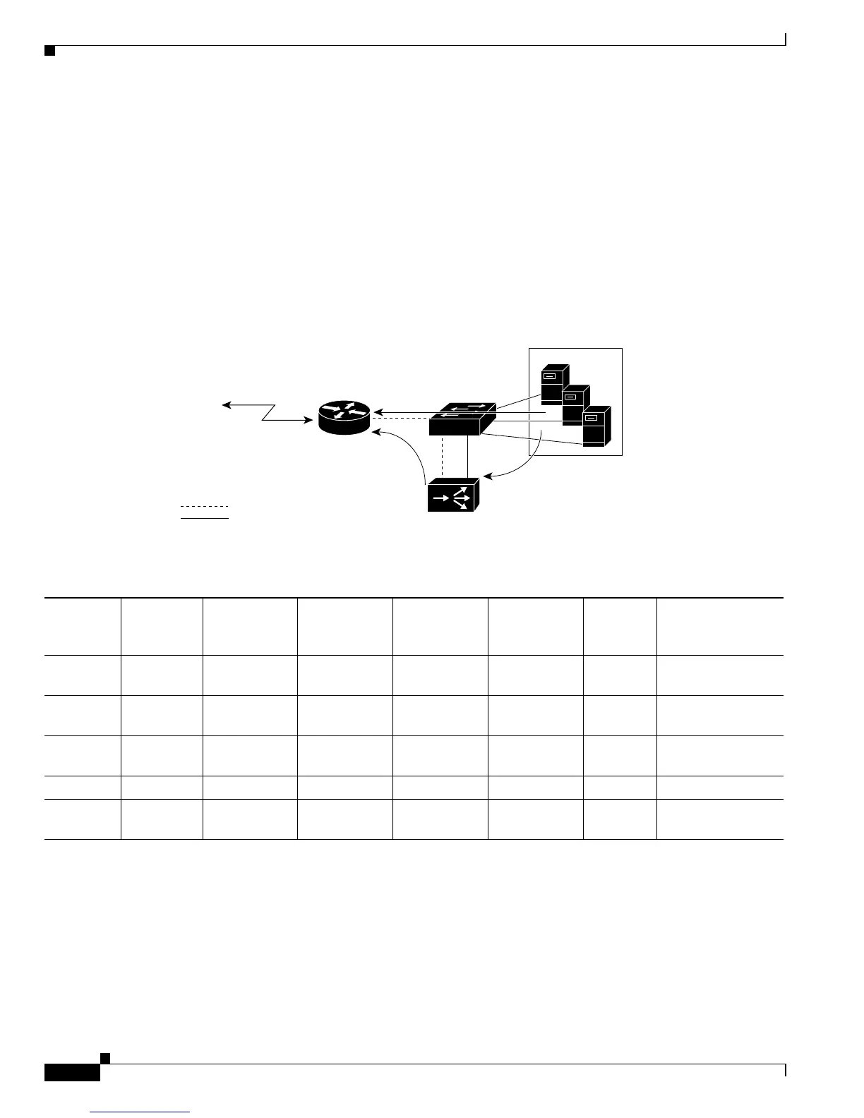
Figure 54-3 shows how data is forwarded from the servers to the clients. Table 54-4 lists the sequence
of events, and Table 54-5 lists the Layer 3 table entries.
The traffic from the servers to the router or client devices works in the same manner, but in the reverse
direction, as described in the “Client-to-Server Data Forwarding” section on page 54-4. The exception
is that the LocalDirector put its own MAC address as the source of the packet for all the packets that are
going to the router. For the traffic in the client-to-server direction, the source MAC address of the packet
was unmodified.
Figure 54-3 Server-to-Client ASLB Packet Flow
Table 54-4 Server-to-Client ASLB Packet Flow
Path
Number VLAN
MAC
Destination
Address
MAC Source
Address
IP Destination
Address
IP Source
Address Flags Action
120Router MAC
1
1. This MAC address has an Xtag value of 14 in the Layer 2 table for this packet’s VLAN.
Server MAC
2
2. The MAC address of the server that the LocalDirector selected.
CIP
3
3. CIP = client’s IP address.
VIP
4
4. VIP = virtual-IP address.
SYN Candidate entry in
Layer 3 table
2 10 Router MAC LocalDirector
MAC
1
CIP VIP - Enabler packet
3—N 20 Router MAC
1
Server MAC CIP VIP - Full ASLB MLS
entry created
N + 1 20 Router MAC
1
Server MAC CIP VIP FIN/RST Path 1 redirect
N +2... 10 Router MAC LocalDirector
MAC
1
CIP VIP FIN/RST Path 2
 Loading...