20-61
Catalyst 6500 Series Switch Software Configuration Guide—Release 8.7
OL-8978-04
Chapter 20 Checking Status and Connectivity
Configuring the Ethernet Local Management Interface
In a MEN, the EVC status is determined by the OAM protocol. In the Catalyst operating system,
ELMI relies on CFM to provide an end-to-end status of the EVC across CFM domains (PE device)
in MEN and updates the CE device through ELMI.
Note The Catalyst operating system supports ELMI only in the PE mode.
• User Network Interface (UNI)—UNI is the physical demarcation point between the service provider
and the customer. Its attributes, which are similar to the UNI identifier and UNI type, are defined on
the PE port that connects to the CE device. The ELMI protocol runs on the UNI interface.
ELMI does the following:
• Notifies the CE when an EVC is added.
• Notifies the CE when an EVC is deleted.
• Notifies the CE of the availability of a configured EVC (Active, Not Active, or Partially Active).
• Communicates UNI and EVC attributes to the CE.
Configuring ELMI
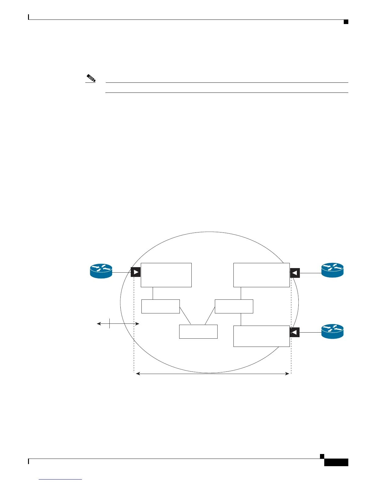
Figure 20-4 shows an example of ELMI that is configured in a multipoint EVC network.
Figure 20-4 ELMI Configured in a Multipoint EVC Network
These guidelines apply to Figure 20-4:
• PE1, PE2, and PE3 are PE switches in the MEN.
PE-1
WS-C6509
WS-SUP720-3BXL
UNI-A
UNI-C
UNI-B
4/4 11/38
3/37 5/1
4/13
11/24
Ge0/1
Ge0/1
Ge0/1
CE1
ISR 3845
CE3
ISR 3845
CE2
ISR 3845
P-core-A
P-core-B
E-LMI
5/6
5/3
4/5
MEN
CFM
189880
P-Core-C
PE-2
WS-C6509
WS-SUP32-10GE-3B
PE-3
WS-C6513
WS-SUP720-3BXL
 Loading...