7-3
Catalyst 6500 Series Switch Software Configuration Guide—Release 8.7
OL-8978-04
Chapter 7 Configuring Spanning Tree
Understanding How Spanning Tree Protocols Work
Understanding How a Topology is Created
All switches in an extended LAN participating in a spanning tree gather information about other
switches in the network through an exchange of data messages that are known as bridge protocol data
units (BPDUs). This exchange of messages results in the following actions:
• A unique root switch is elected for the spanning-tree network topology.
• A designated switch is elected for every switched LAN segment.
• Any loops in the switched network are eliminated by placing redundant switch ports in a backup
state; all paths that are not needed to reach the root switch from anywhere in the switched network
are placed in STP-blocked mode.
The topology of an active switched network is determined by the following:
• The unique switch identifier Media Access Control ([MAC] address of the switch) that is associated
with each switch
• The path cost to the root that is associated with each switch port
• The port identifier (MAC address of the port) that is associated with each switch port
In a switched network, the root switch is the logical center of the spanning-tree topology. A
spanning-tree protocol uses BPDUs to elect the root switch and root port for the switched network, as
well as the root port and designated port for each switched segment.
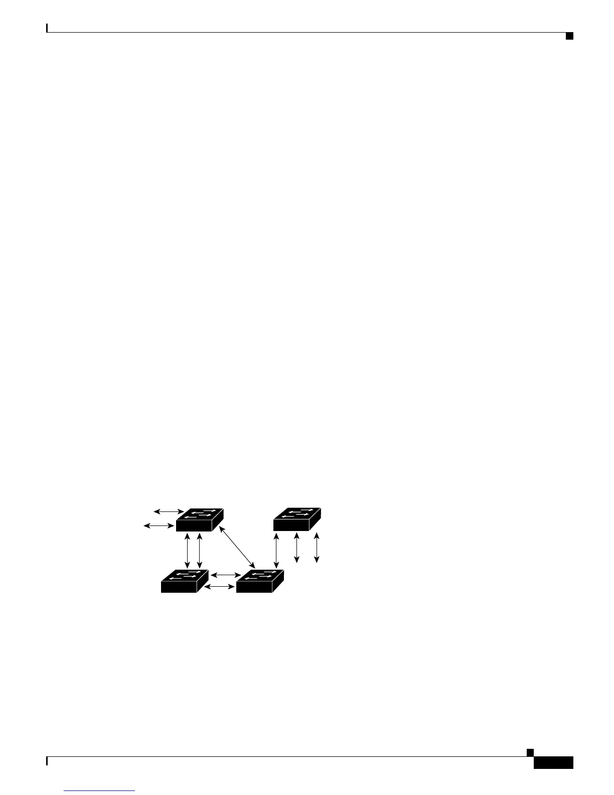
Understanding How a Switch Becomes the Root Switch
If all switches are enabled with default settings, the switch with the lowest MAC address in the network
becomes the root switch. In Figure 7-1, Switch A is the root switch because it has the lowest MAC
address. However, due to traffic patterns, number of forwarding ports, or line types, Switch A might not
be the ideal root switch. A switch can be forced to become the root switch by increasing the priority (that
is, lowering the numerical priority number) on the preferred switch. This action causes the spanning tree
to recalculate the topology and make the selected switch the root switch.
Figure 7-1 Configuring a Loop-Free Topology
You can change the priority of a port to make it the root port. When the spanning-tree topology is based
on default parameters, the path between the source and destination stations in a switched network might
not be ideal. Connecting higher-speed links to a port that has a higher number than the current root port
can cause a root-port change. The goal is to make the fastest link the root port.
 Loading...