Copyright 2013 Baker Hughes Company.
English–DPI620G Instruction Manual | 109
HART® Menu Operations
9. HART® Operations
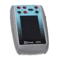
The DPI620G can work with devices that use the HART protocol:
• The Universal and Common Practice instructions specified in HART versions 5 to 7.
• Devices that use Device Descriptions (DD).
This chapter has procedures for how to use the HART functions available in the calibrator.
The instructions for the use of HART in the DPI620G-IS are at the end of this chapter. See
Section 9.11 on page 130.
9.1 HART® Menu Operations
The HART protocol uses a digital signal mixed with a standard 4 - 20mA current loop, to transmit
data to and from a field device that uses HART communication. Typical operations are:
• Read the primary variable and the analog output.
• Read the device serial number, type and supplier.
• Get calibration data from memory (upper and lower range values, sensor limits, calibration
date).
• Do status and fault-finding checks.
• Change the device setup (range, units, damping).
You can use the DPI620G as an interface with other HART field devices:
• As a Primary Master. The DPI620G starts and controls all transmitted signals. The field
device (slave) uses each command from the master device to make a change and/or send
data back.
• As a Secondary Master. The DPI620G connects to a HART network. The Secondary Master
controls signals with the field device in between Primary Master messages.
9.2 Start-up
Tap the COMMUNICATOR icon on the Dashboard and then tap the HART
icon on the Dashboard to start the HART control of signals.
Tasks can be selected for CH1, CH2, P1, P2 and external sensor. Refer to Chapter 3.
You can also select HART from the TASK MENU screen. Tap the CUSTOM TASK menu row
a
n
d then tap the HART row if it is available on the screen.
9.3 HART® Connections
Before the electrical connections between the HART device and the DPI620G are set, select the
correct connection scheme (Refer to DASHBOARD > HELP). Refer to Chapter 9.11 on page 130
for information that relates to the DPI620G-IS equivalents.
9.3.1 Power Supply from the Calibrator
A 24V or 28V loop power can be supplied to the HART device: use the CH2 Current (24V or 28V)
me
asure function.
HART® Operations

 Loading...