Copyright 2013 Baker Hughes Company.
English–DPI620G Instruction Manual | 131
How to connect a DPI620G-IS to HART® compatible devices
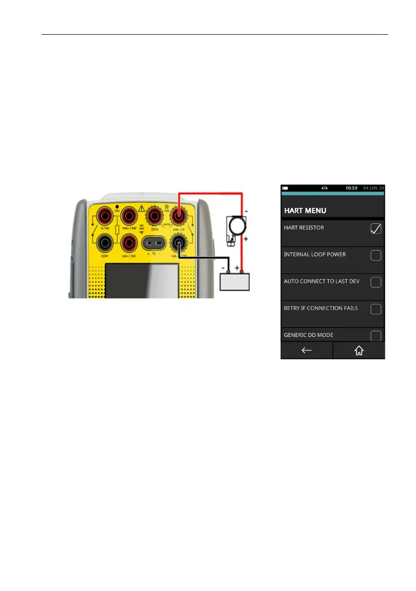
9.11.2 Transmitter - External Loop Supply with Current Measure
In this example an external power supply supplies the loop power and the DPI620G-IS makes
av
ailable the 250Ω HART resistor.
• Use the instructions in Section 9.2 on page 109 and Section 9.3 on page 109 to prepare the
instrument to use the HART function.
• Tap on the CUSTOM TASK to select this mode.
• Set the communicator channel CH2 to None.
• Set the communicator channel to HART.
• Set the internal HART resistor to ON: use an on-screen checkbox to do this. This lets HART
data be transmitted when connection is made in this mode with the DPI620G-IS.
This instrument measures the current in the Current Loop. If an external HART resistor is
a
v
ailable, use the connection method given in “Active HART Current Loop” on page 130..
Figure 9-31: Connection with External Loop Supply
The effect of a voltage drop must be included because of the loop impedance in relation to the
tr
ansmitter operating voltage. (The loop impedance is made up of the 250Ω HART resistor in
series with the output impedance of the power supply).
 Loading...