Copyright 2013 Baker Hughes Company.
English–DPI620G Instruction Manual | 137
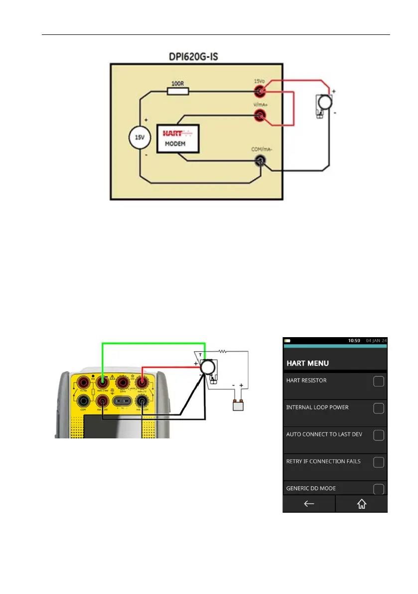
How to connect a DPI620G-IS to HART® compatible devices
Figure 9-38 shows a diagrammatic representation of the loop:
Figure 9-38: Internal Loop Supply - Parallel Connection - CH1 Current Measurement
9.11.6 Transmitter - Test Connection
To use the Test connection on a HART® transmitter: use CH1 to measure current and CH2 to
c
o
mmunicate with the HART device. Follow these instructions:
• Use the instructions in Section 9.2 on page 109 and Section 9.3 on page 109 to prepare the
instrument to use the HART function.
• Tap on the CUSTOM TASK to select this mode.
• Set the CH1 channel to Current Measure and the CH2 channel to None.
• Make sure that HART RESISTOR is not selected (Checkbox must be empty).
• Make sure that INTERNAL LOOP POWER is not selected (Checkbox must be empty).
Figure 9-39: HART IS Test Connection
 Loading...