Copyright 2013 Baker Hughes Company.
64 | DPI620G Instruction Manual–English
Chapter 4. Electrical Tasks
4.9.2 DPI620G-IS Measure or Simulate a Resistance Temperature Detector (RTD)
Figure 4-2
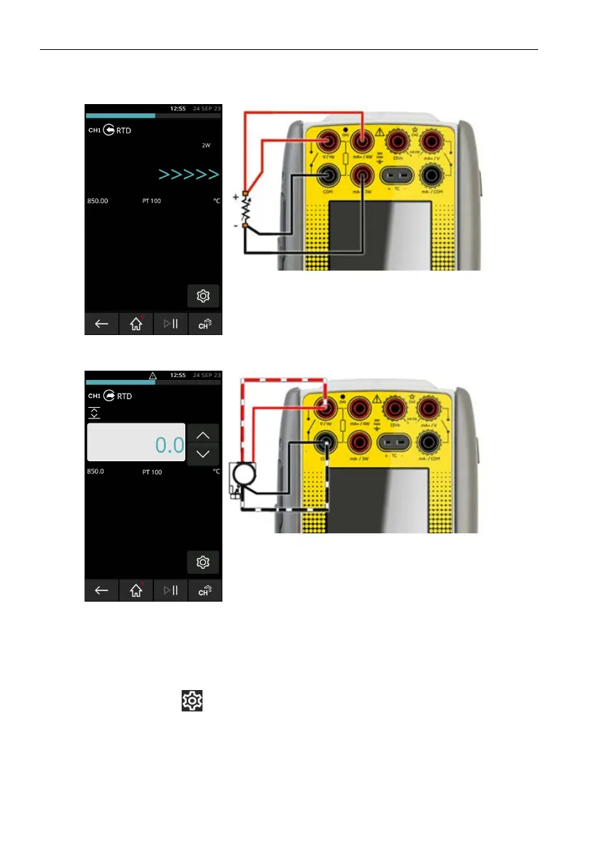
7 and Figure 4-28 show CH1 set to measure an RTD. A 4-wire setup gives the best
accuracy; a 2-w
ire configuration has the lowest accuracy.
Figure 4-27: PT100 RTD Measure CH1 4-Wire (Range -200 to 850°C)
Figure 4-28: PT100 RTD Source CH1 4-Wire (Range -200 to 850°C)
1. Set the applicable software options: CH1, Measure/Source, RTD, Units.
2. Complete the electrical connections.
3. If necessary, change the RTD Type (default is PT100).
Select the SETTINGS icon on the Dashboard, then tap RTD TYPE and select the type
of RTD sensor.
 Loading...