Copyright 2013 Baker Hughes Company.
English–DPI620G Instruction Manual | 111
HART® Connections
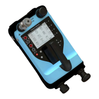
9.3.3 Communicator Attached to a Network
In this example the calibrator connects directly to a network. There must be a 250Ω resistor in
se
ries with the loop power supply and the HART device.
Figure 9-3: HART Communicator Network Connection
CH2 function is set to None. The HART function is made available on the HART channel with the
2
5
0Ω resistor set to Off.
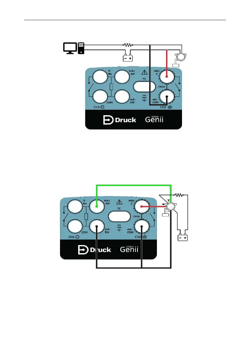
9.3.4 Use of Test Connections
To use the test connection on a HART transmitter: use CH1 to measure current and CH2 as the
si
gnal interface with the HART device. The CH2 function must be set to None, and the CH1
fu
nction must be put into Current Measure mode. There must be an external HART resistor in
th
e loop.
Figure 9-4: HART Device Test Connections

 Loading...