Copyright 2013 Baker Hughes Company.
74 | DPI620G Instruction Manual–English
Chapter 5. Pressure Tasks
5.2.1 Assembly Instructions
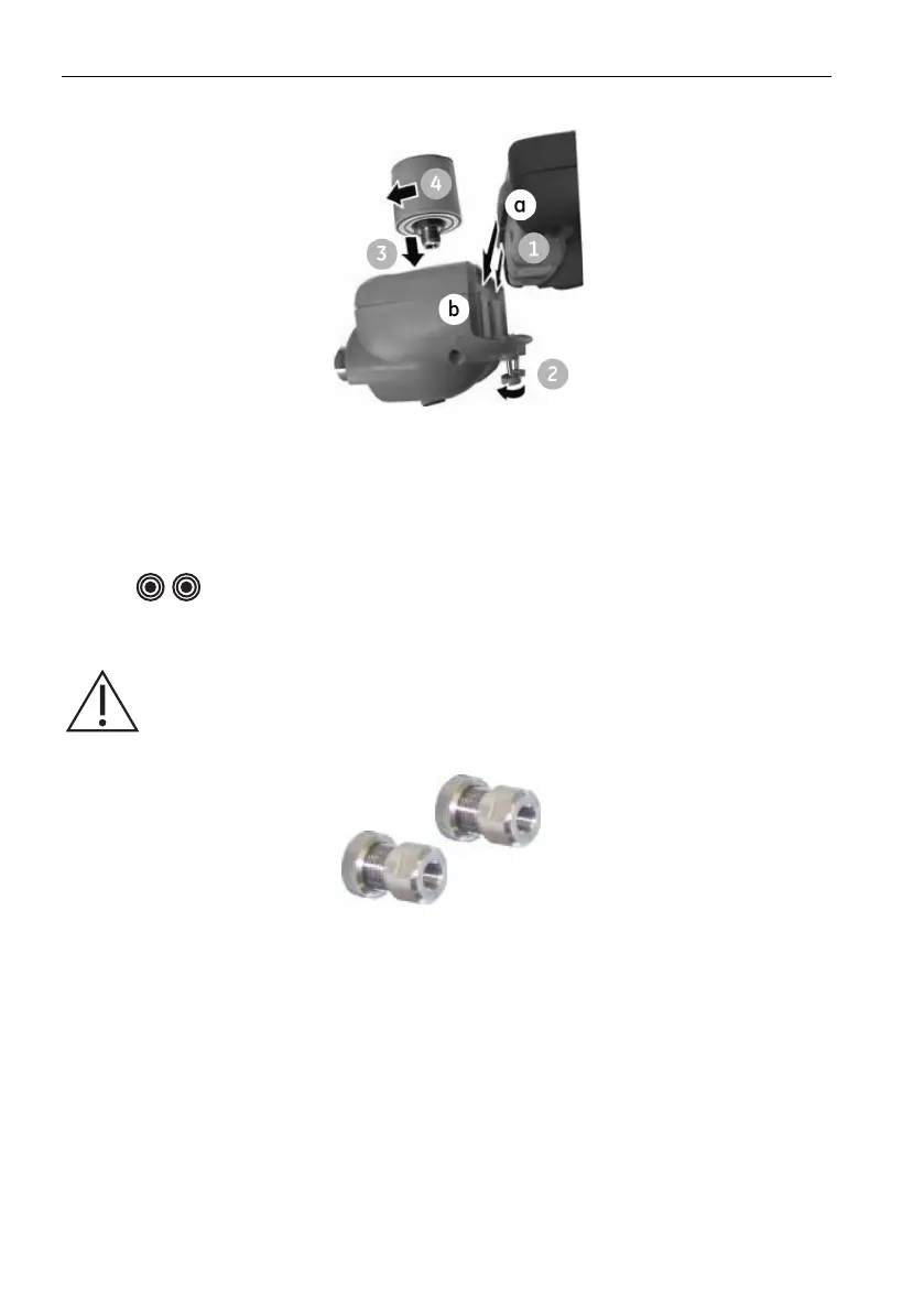
Figure 5-6: MC620G Assembly Procedure
1. Align the two slots (a) on the calibrator with the two posts (b) on the module carrier.
2. When the posts are fully engaged in the slots, tighten the two screws (2) hand tight.
3. Attach one or two PM620 / PM620T modules (4) with the correct range and type.
4. Tighten each PM620 / PM620T module (4) hand-tight only.
5. The symbol flashes at the top of the screen, when the communication link between
the PM620 / PM620T module and the calibrator occurs.
5.3 Pressure Connections
Use “Quick fit” pressure adapters on the pressure ports for external equipment. See Figure 5-7.
Figure 5-7: Quick Fit Pressure Adapter
1. Remove the adapter from the pressure port.
2. Use an applicable seal for the pressure connection:
a. NPT type: Use an applicable sealant on the thread.
b. BSP (parallel) type: Use the applicable bonded seal at the bottom.
c. BSP (parallel) type, 100 bar (1500 psi) or less: a bonded seal at the top is permitted.
3. Attach the adapter to the external equipment. If necessary, use an alternative adapter.
4. Tighten to the applicable torque.
WARNING Pressurized gases and fluids are dangerous. Always safely release
all the pressure, before attachment or disconnection of pressure equipment.

 Loading...