Copyright 2013 Baker Hughes Company.
34 | DPI620G Instruction Manual–English
Chapter 3. Calibrator
3. Calibrator
3.1 Basic Calibrator Operation
Tap the CALIBRATOR icon on the Dashboard to show the CALIBRATOR screen.
3.1.1 Layout
The calibrator screen shows measurement or source functions which are in channel groups. More
th
an one channel can be on the calibrator screen. These six channels are available:
• *Electrical - Channels “CH1” and “CH2”.
• Pressure (via PM620 / PM620T and MC620G) - Channels “P1” and “P2”.
• External Sensor (USB) - supports sensors such as TERPS, IDOS or RTD-INTERFACE.
• Communications - supports HART®, FOUNDATION™ Fieldbus and Profibus®.
* The DPI620G-B has only one electrical channel, CH, which is equivalent to the DPI620G CH2
c
h
annel.
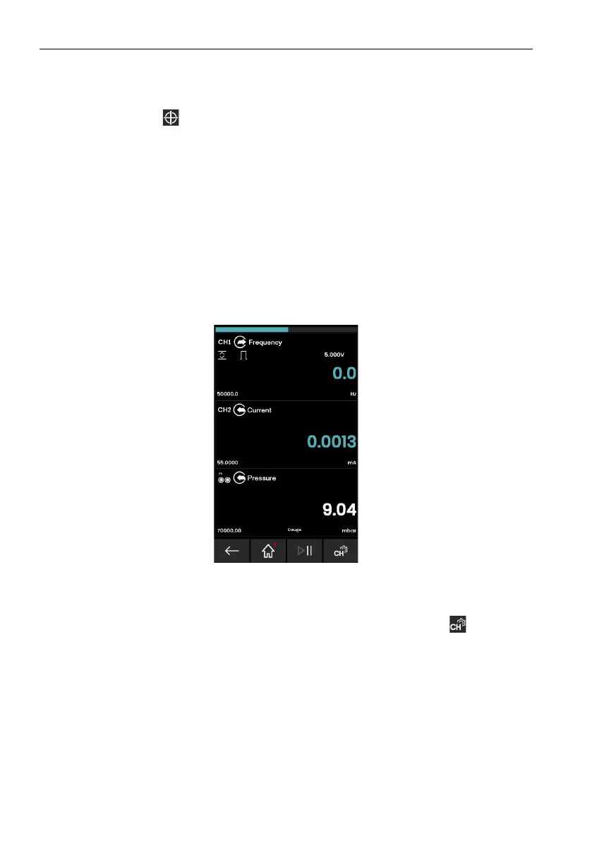
There are two display views (normal and expanded) in the CALIBRATOR screen when multiple
ch
annels are in use. Figure 3-1
shows a normal view with three selected channels.
To expand the view of a channel, tap in the area of the channel window.
Figure 3-1: Calibrator Window – Normal View (Three Channels)
To show the TASK MENU (Section 3.3 on page 37) screen, you can either swipe your finger from
right to left (
) on the CALIBRATOR screen or tap the CHANNEL SETTINGS icon in the
bottom right corner of the display.
Calibrator
 Loading...