Copyright 2013 Baker Hughes Company.
138 | DPI620G Instruction Manual–English
Chapter 9. HART® Operations
The test connection in the transmitter can be +ve or -ve. Figure 9-39 shows a connection for a
+ve Test terminal. For a -ve Test terminal, the Test terminal must connect to the CH1 mA-
te
rminal and the CH1 mA+ connect to the transmitter +ve terminal.
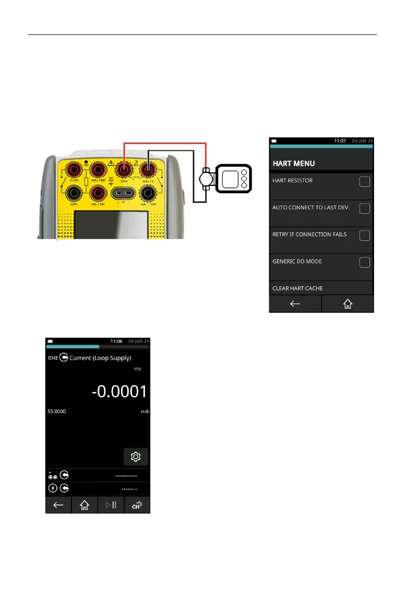
9.11.7 Positioner - Internal Loop Power Supply with Current Source
In this example, the internal power supply is the source of the loop power. The output impedance
of
the internal power supply and the current sourcing circuit, supply the loop impedance for the
HART function. Use this connection method for all devices that are powered (and controlled) by
a current source..
Figure 9-40: Positioner Connection with Internal Loop Supply
•Use the instructions in Section 9.2 on page 109 and
Section 9.3 on page 109 to prepare the instrument to use
the HART function.
•Tap on the CUSTOM TASK to select this mode.
•Set the CH2 function to Current Source (Loop Supply). Set
the current to the minimum input current (typically 4mA).
•Make sure that HART RESISTOR is not selected
(Checkbox must be empty).
•Make sure that INTERNAL LOOP POWER is not selected
(Checkbox must be empty)
For these devices, it is important that the DPI620G-IS is in
c
u
rrent source mode and operates as a controlled current
source. If the DPI620G-IS is in current measure mode, the
device under test will take the maximum current given by the
power supply: HART data transmission is not possible. To
control the positioner, the source current can be set
between 4 mA and 20mA.
 Loading...