Copyright 2013 Baker Hughes Company.
English–DPI620G Instruction Manual | 139
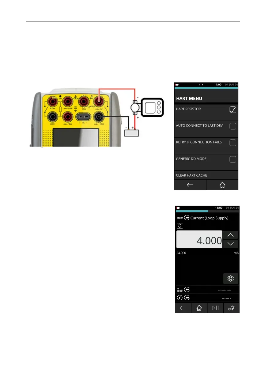
How to connect a DPI620G-IS to HART® compatible devices
9.11.8 Positioner - External Loop Supply with Current Source
In this example, an external power supply supplies the loop power. The loop impedance
ne
cessary for the HART function is given by the current sourcing circuit and optional internal
HART resistor. This connection method should be used for all devices that are powered (and
controlled) by a current source.
In this example, an external power supply supplies the loop power. The loop impedance for the
HA
RT function is supplied by the current sourcing circuit and an optional internal HART resistor.
Use this connection method for all devices that are powered (and controlled) by a current source.
Figure 9-41: Positioner Connection with External Loop Supply
• Use the instructions in Section 9.2 on page 109 and
Section 9.3 on page 109 to prepare the instrument to use
the HART function.
• Tap on the CUSTOM TASK to select this mode.
• Set the CH1 channel to Current Measure.
• Set the CH2 function to Current Source (Loop Supply). Set
current to the minimum input current (typically 4mA).
• Make sure that HART RESISTOR is ON (Checkbox must
have a tick mark in it).
• Make sure that INTERNAL LOOP POWER is not selected
(Checkbox must be empty).
For these devices, it is important that the DPI620G-IS is in
c
u
rrent source mode and operates as a controlled current
source. If DPI620G-IS is in current measure, the device under
test will take the maximum current from the power supply: HART
communications cannot be used. To control the positioner, set
the source current between 4 mA and 20mA.
 Loading...