Copyright 2013 Baker Hughes Company.
English–DPI620G Instruction Manual | 161
Introduction
11. Profibus® PA
11.1 Introduction
The DPI620G can communicate with devices that use Profibus® PA Fieldbus implementation.
This is done by the use of an integrated modem.
Note: The modem hardware is only included in DPI620G-PB or DPI620G-FFPB.
This chapter gives information of how to connect the Profibus® PA device to the DPI620G and
D
P
I620G-IS.
11.2 Profibus® Configurations
The correct configuration must be done before the setup of the electrical connections between
the Profibus® device and the DPI620G/DPI620 IS.
The DPI620G-IS can work with devices that use the PROFIBUS PA Fieldbus implementation.
Thi
s is done by the use of an integrated modem.
Note: The IS modem hardware is only included in DPI620G-IS-PB or DPI620G-IS-FFPB.
A Profibus® network at its simplest consists of a field device, two terminators and a power supply.
Th
i
s lets the connection of the DPI620G or DPI620G-IS to:
• Connect with an existing network where the power supply and termination are available.
• Connect with Stand-alone Profibus® PA devices.
• Connect networks in between.
11.3 Start-up
To start Profibus®, select the Profibus® application icon from the Dashboard screen.
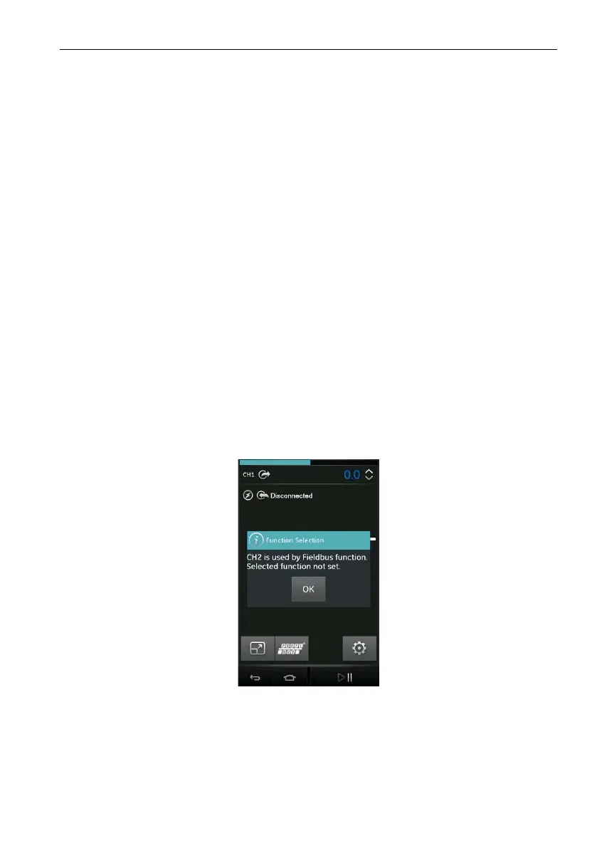
CH2 automatically stays in the Volts measure mode. To try to select a function on CH2 will be a
fa
ilure: the display will show an information message and the selected function will not be
available.
Figure 11-1: CH2 Function Not Set when Profibus® is Enabled
Profibus® can also be selected from the Calibrator Task Menu by selecting the Profibus® option
i
n
the Field Communications channel.
Note: Volts measure or None are the only valid modes for CH2 when PROFIBUS® is
operational.
Profibus® PA
 Loading...