Copyright 2013 Baker Hughes Company.
English–DPI620G Instruction Manual | 189
Procedures (CH1): Resistance (Measure)
c. Do a check to find if the error is in the limit range. Refer to Table 12-10.
12.8 Procedures (CH1): Resistance (Measure)
Use this procedure:
1. Connect the applicable calibration equipment. Refer to Table 12-1.
2. Let the equipment get to a stable temperature (minimum: 5 minutes since the last power on).
3. Use the Calibration menu (see Section 12.1) to do a two-point resistance measure
calibration:
a. Range: 0 - 400Ω
• Nominal zero ohms - make a 4-wire connection to the 0Ω.
• Nominal positive full-scale ohms - make a 4-wire connection to the 400Ω resistor.
b. Range: 400 Ω - 4kΩ
• Nominal 400Ω - make a 4-wire connection to the 400Ω resistor.
• Nominal positive full-scale ohms - make a 4-wire connection to the 4kΩ resistor.
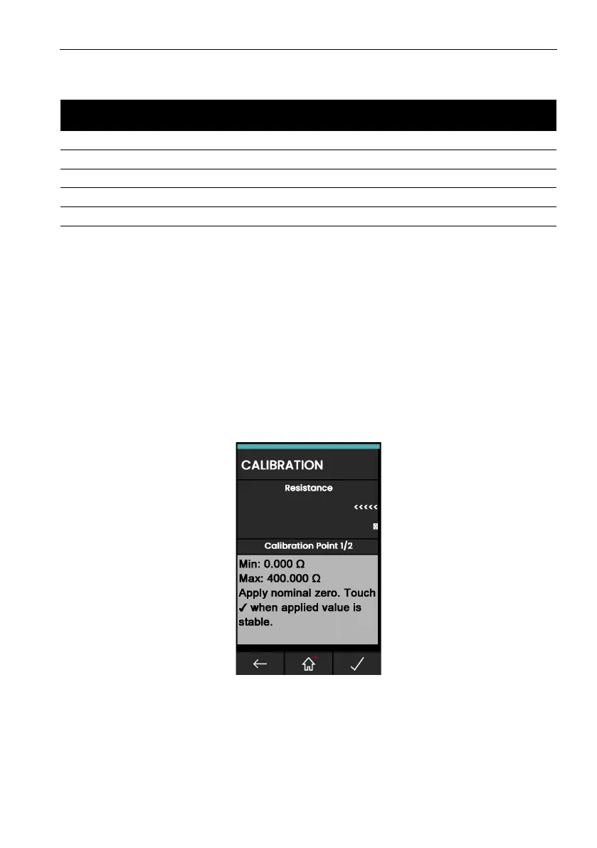
Figure 12-8: Calibration – Resistance Measure CH1 (Range: 400Ω)
4. Do a check to make sure that the calibration is correct:
a. Select the applicable Resistance (measure) function via the Calibrator Task menu.
b. Make a 4-wire connection to the applicable standard resistor and measure the value.
Table 12-10: Amplitude (Source) Error Limits
Amplitude Volts
(V)
Calibrator Uncertainty
(V)
Permitted DPI620G
Error (V)
Permitted DPI620G-IS
Error (V)
0.2 0.01 [0.000004] 0.1 [0.1]
5.0 [3] 0.01 [0.000019] 0.1 [0.1]
[6.0] 0.01 [0.000034] 0.1 [0.1]
10.0 [9] 0.01 [0.000049] 0.1 [0.1]
20.0 [12] 0.01 [0.000064] 0.1 [0.1]
 Loading...