Step 1: Blade Fibre Channel cables
115
Connect Cables for a Direct-connected VG8
EMC CONFIDENTIAL
Connecting a
VNX5300 or
VNX5500 array
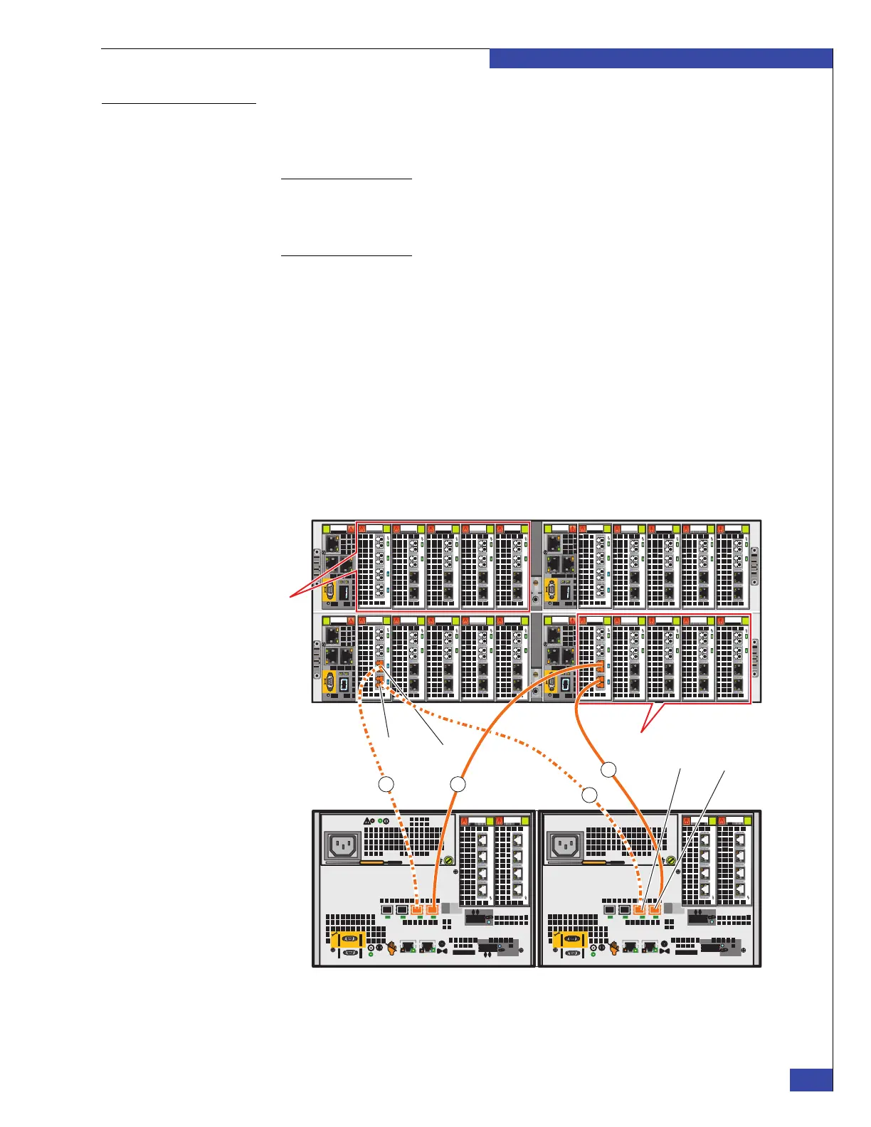
Figure 79 on page 115 shows an example of a VNX5300/VNX5500 array. Connect the
Fibre Channel cables from the I/O modules in the blades to the array SPs. Use SFPs to
connect the ports (“SFP modules” on page 43 provides more information):
Note: Figure 79 on page 115 shows only the first four cable connections for
illustration purposes. The following steps describe how to connect the cables for a
VNX VG8 configuration with 4 blades. The maximum number of connections
depends on the availability of ports in the SPs.
1. Connect blade 2 slot 0, port 0 to SP A, port 5 (cable 1 in Figure 79 on page 115).
2. Connect blade 2 slot 0, port 1 to SP B, port 5 (cable 2 in Figure 79 on page 115).
3. Connect blade 3 slot 0, port 0 to SP A, port 4 (cable 3 in Figure 79 on page 115).
4. Connect blade 3 slot 0, port 1 to SP B, port 4 (cable 4 in Figure 79 on page 115).
5. Connect blade 4 slot 0, port 0 to SP A, port 3.
6. Connect blade 4 slot 0, port 1 to SP B, port 3.
7. Connect blade 5 slot 0, port 0 to SP A, port 2.
8. Connect blade 5 slot 0, port 1 to SP B, port 2.
Figure 79 FC cables connect VNX VG8 blades to VNX5300/VNX5500 array (example)
0
123
0
1
23
0
1 23
0
12 3
0
12 3
0
123
0
1 23
0
1
23
0
1 23
0
1 23
0
123
0
1
23
0
1 23
0
12 3
0
12 3
0
123
0
1 23
0
1
23
0
1 23
0
1 23
SP ASP B
DPE
Blade 5
Blade 2
Port 0
Port 1
AB
1 X4
2
3
4
5
6Gb
SAS
8Gb
bre
0 X4
6Gb SAS
2
3
4
5
6Gb
SAS
8Gb
bre
0 X4
6Gb SAS
1 X4
0
1
2
3
0
1
2
3
0
1
2
3
0
1
2
3
3
4
VNX5300/VNX5500
VNX VG8
1
2
Port 5Port 4
 Loading...