Step 1: Check components
39
Before Installing
EMC CONFIDENTIAL
VG2/VG8 Control
Station
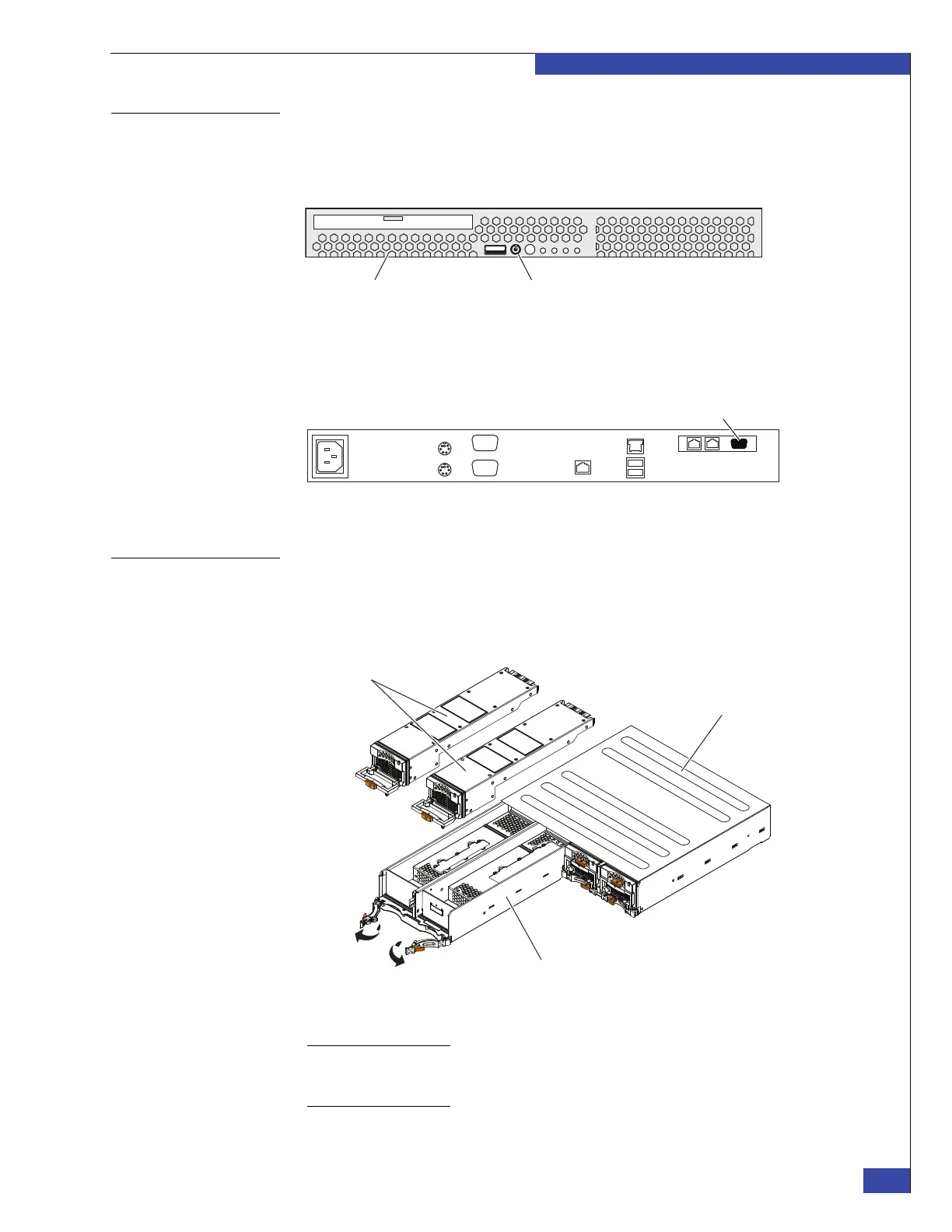
Each VG2/VG8 system can have one or two Control Stations. Figure 9 shows the
front view of the VG2/VG8 Control Station. Note the location of the power button
(also known as the reset button).
Figure 9 VG2/VG8 Control Station front view
Figure 10 shows the rear view of the VG2/VG8 Control Station. Note the location of
the serial console.
Figure 10 VG2/VG8 Control Station rear view
VG2/VG8 CPU and
power supply/
cooling modules
The VG2/VG8 blade enclosure can house two blades, and each blade is associated
with a CPU module (viewed from the front of the cabinet). Each blade CPU
(Figure 11) accommodates two power supply/cooling modules, which provide
power and cooling for the I/O modules that are associated with the blade.
Figure 11 CPU and power supply/cooling modules
Note: The VG2 provides only one blade enclosure, which usually contains two blades; if a
one-blade system is ordered, a CPU filler assembly occupies the location of the blade CPU. See
example in Figure 5 on page 36.
Control Station (front) Power button CNS-000876
1
1
1
1
2
2
2
CNS-001636
Power supplies
Blade enclosure
Blade CPU
 Loading...