Step 5: External network cables
123
Connect Cables for a Direct-connected VG8
EMC CONFIDENTIAL
Step 5: External network cables
The external network cables connect clients of the VNX system to the I/O modules in
the blades. Another external network cable connects the Control Station to the
customer’s network for remote management of the system.
Note: For successful blade failover, you must establish identical network connections for the
primary and standby blades.
The external network cables are provided by the customer. The category and
connector type of the cable must be appropriate for use in the customer network.
The VG8 system has these I/O module types:
◆ Two 10 GbE optical ports (Figure 14 on page 42).
◆ Four 1 GbE copper 10/100/1000 ports (Figure 15 on page 42).
◆ Two 1 GbE copper 10/100/1000 ports and two optical 1 GbE ports (Figure 16 on
page 43).
The copper Ethernet network ports on the blades support 10, 100, or 1000 megabit
connections and have standard RJ-45 connectors.
The optical Gigabit Ethernet network ports have LC optical connectors and support
50 or 62.5 micron multimode optical cables. SFP modules are installed at the factory
(see “SFP modules” on page 43 for more information).
Any advanced configuration of the external network ports is beyond the scope of this
setup guide. The VNX system supports many network configuration options such as
Ethernet channels, link aggregation, and Fail-Safe Networks (FSNs). The Configuring
and Managing Celerra Networking and Configuring and Managing Celerra Network High
Availability technical modules provide more information.
To connect the external network cables:
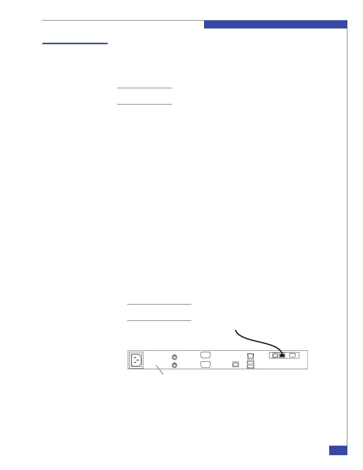
1. Connect the Ethernet LAN cable (labeled MGMT) on the first CS to the
customer’s 10/100 Ethernet network that will be used to manage the VNX VG8
gateway. On factory-installed systems, this cable is connected to the MGMT port
on CS 0 (Figure 88).
Note: You can also disconnect the connected cable and directly connect a cable supplied by
the customer.
Figure 88 External network connection on Control Station
2. For dual Control Station systems, connect the cable from the MGMT port of CS 1
to the customer’s 10/100 Ethernet network. If possible, the two CSs should
connect to different Ethernet switches in the customer’s network for high
availability.
To Public LAN
CIP-001143
Control Station
 Loading...