EMC VNX VG2/VG8 Gateway Configuration Setup Guide
38
Before Installing
EMC CONFIDENTIAL
VG8 components
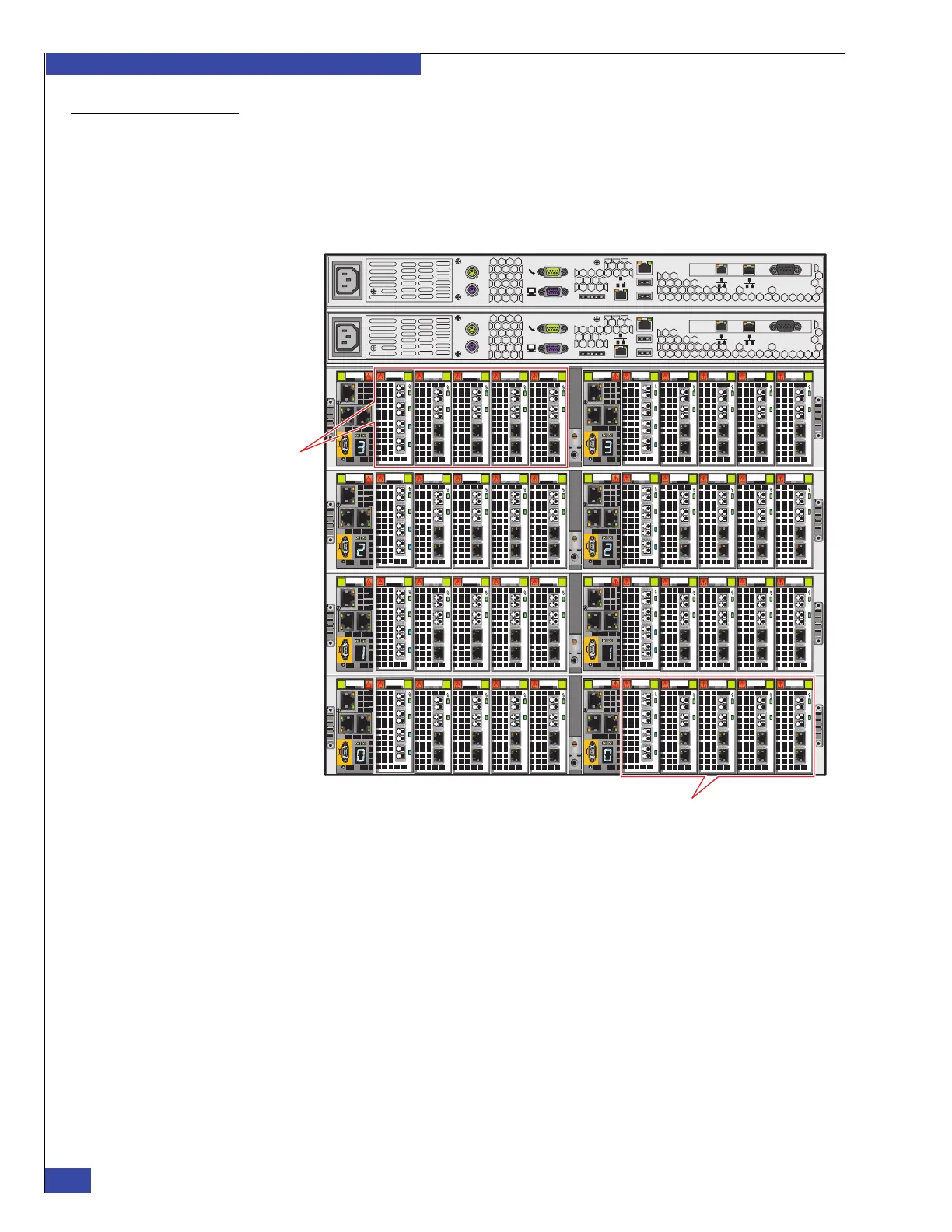
Figure 8 shows an VG8 system with two Control Stations, four blade enclosures, and
eight blades (the maximum configuration for this system). In the VG8 system, the
first blade enclosure must have two blades (unlike the VG2 system, which can have
one or two blades). Each blade can have from one to five I/O modules; a mix of
different I/O module types is possible. The specific combination of I/O modules
within a blade must be the same for all blades within the system.
Figure 8 Example of VNX VG8 system—eight blades and two CSs (rear)
Serial
console
MGMT
CS
B
MODEM plug
VGA socket
A
Serial
console
MGMT
CS
B
MODEM plug
VGA socket
A
0
123
0
1
23
0
1
23
0
12 3
0
12 3
0
123
0
1 23
0
1
23
0
1 23
0
1 23
0
123
0
1
23
0
1
23
0
12 3
0
12 3
0
123
0
1 23
0
1
23
0
1 23
0
1 23
0
123
0
1
23
0
1
23
0
12 3
0
12 3
0
123
0
1 23
0
1
23
0
1 23
0
1 23
0
123
0
1
23
0
1
23
0
12 3
0
12 3
0
123
0
1 23
0
1
23
0
1 23
0
1 23
Blade 9
Blade 2 CNS-001646
 Loading...