EMC VNX VG2/VG8 Gateway Configuration Setup Guide
36
Before Installing
EMC CONFIDENTIAL
VG2 components
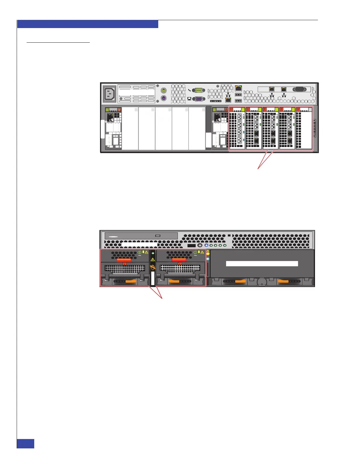
Figure 4 shows the rear view of an VG2 system that is equipped with one Control
Station and one blade in a single blade enclosure. When only one blade is equipped,
I/O filler panels are required in the unused half of the blade enclosure (as shown) to
meet air flow requirements.
Figure 4 Example of VNX VG2 system with one blade (rear view)
Figure 5 shows the front view of the same VG2 system that is shown in Figure 4. In
this example, a CPU/power supply filler assembly fits into the space where a CPU
module and its associated power supply/cooling modules would go if both blades
were equipped in the enclosure.
Figure 5 Example of VNX VG2 system with one blade (front view)
Serial
console
MGMT
CS
B
MODEM plug
VGA socket
A
0
123
0
1 23
0
1 23
0
1 23
0
1
23
Control Station 0
Blade (Data Mover)
CNS-001642
AC
AC
DVD
AC
Control Station 0
CPU/power supply filler assembly
CPU module with power supply/
cooling modules
AC
CNS-001640
 Loading...