Component layout
55
Install Components in Customer’s Cabinet
EMC CONFIDENTIAL
Begin with the lowest component in the cabinet and work towards the top. The VNX
gateway, FC/FCoE switches, and arrays do not have to be in the same cabinet.
If you are installing a new Symmetrix or VNX array at the same time, refer to the
appropriate installation documentation for the array.
Component layout
The relative position of the components within the rack is not critical as long as:
◆ Cables can reach connecting ports or receptacles
◆ Access to connections at the rear of the cabinet is possible
Note: Enclosures have different depths. You should stack enclosures within the cabinet to
facilitate access to the rear of the components.
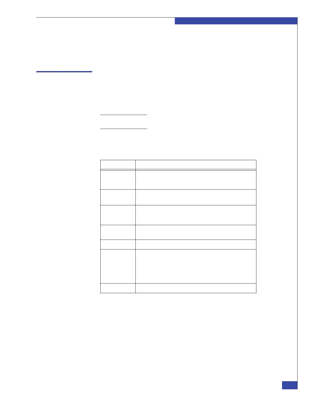
Table 4 provides information about the VG2/VG8 components and examples of
stacking these components.
When the system first boots, the Control Station assigns the blade identifiers based on
the management module ports to which the blades are connected. The blades then
store their identities in the memory of the blade enclosure.
Table 4 Component information
Component Reference
Blade A blade includes the I/O modules that you access from the rear of the
cabinet and an associated CPU module with power supply/cooling
modules that you access from the front of the cabinet.
I/O modules • “Fibre Channel I/O modules” on page 40
• “Network I/O modules” on page 41
CPU module with
power supply/
cooling modules
“VG2/VG8 CPU and power supply/ cooling modules” on page 39
Management
module
“Management module” on page 44
Control Station “Control Station components” on page 35
VG2 examples • Figure 4 on page 36
• Figure 5 on page 36
• Figure 6 on page 37
• Figure 7 on page 37
• Figure 20 on page 45
VG8 example Figure 8 on page 38
 Loading...