EMC VNX VG2/VG8 Gateway Configuration Setup Guide
120
Connect Cables for a Direct-connected VG8
EMC CONFIDENTIAL
Step 4: Private LAN cables
The private (internal) LAN cables connect the Control Station to the blades through
the blade enclosure’s management modules. These cables and switches make up a
private network that does not connect to any external network.
The blade enclosure has two management modules, which are redundant. If module
A fails, module B assumes control of the private network. The Control Stations
communicate to the blades through the management modules.
The VG8 system has an internal network formed by daisy-chaining the management
modules attached to each enclosure. The Control Stations communicate to all blades
through the management modules on both sides of the enclosures.
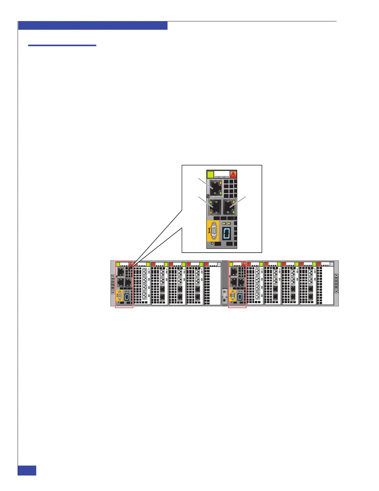
Figure 84 shows the VG8 management module with the private LAN ports 0, 1, and
2.
Figure 84 Management module for blade enclosure
Verify the cables are installed correctly and the connectors are fully seated. Refer to
Figure 85 on page 121 for cabling the Control Station to blade enclosure 0 and
Figure 86 on page 122 for cabling (daisy-chaining) the blade enclosures:
1. Verify that an RJ-45 Ethernet cable connects from port 1 on management module
A in blade enclosure 0 (blades 2 and 3) to the port labeled A on CS 0. This is cable
#1 in Figure 85 on page 121.
2. Verify that an RJ-45 Ethernet cable connects from port 1 on management
module B in blade enclosure 0 (blades 2 and 3) to the port labeled B on CS 0. This
is cable #2 in Figure 85 on page 121.
3. If required, verify that an RJ-45 Ethernet cable connects from port 2 on
management module A in blade enclosure 0 (blades 2 and 3) to the port labeled A
on CS 1. This is cable #3 in Figure 85 on page 121.
0
123
0
123
0
12 3
0
1 23
0
1 23
0
1 23
0
1 23
0
1
23
0
12 3
0
12 3
Management
module B
CNS-001679
Management
module A
Port 1
Port 0
Port 2
 Loading...