GE MEDICAL SYSTEMS
2127661
LOGIQ 400 SERVICE MANUAL
FUNCTIONAL CHECKS
4–40
REV 6
4–4–2 Power Supply Adjustment Procedure
1. Power LOGIQ 400 ON. Wait for about 30 seconds to warm up the console.
2. For each of the power supplies which are located on the LV Unit, connect a DVM to the appropriate place shown in
TABLE 4–1 for the Power Supply Unit, TABLE 4–3 on page 4–42 for the Power Supply Unit 2 or TABLE 4–5 on
page 4–44 for the Power Supply Unit 3.
3. Verify that the voltages are as shown in TABLE 4–2 for the Power Supply Unit, TABLE 4–4 on page 4–42 for the
Power Supply Unit 2 or TABLE 4–6 on page 4–44 for the Power Supply Unit 3, respectively.
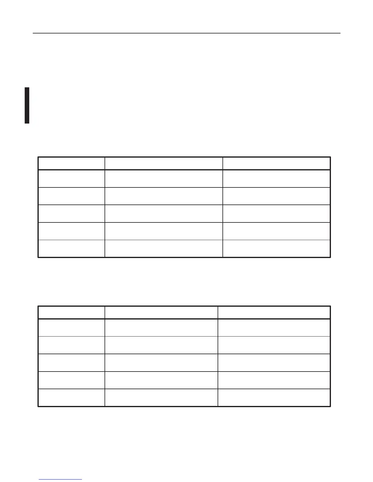
TABLE 4–1
POWER SUPPLY MEASUREMENT LOCATION
POWER SUPPLY MEASURE AT RETURN AT
+5V for Digital
–5V
+12V
+5V for Analog
–12V
+5V Terminal on Power Supply
See ILLUSTRATION 4–31
+5V Terminal on Power Supply
See ILLUSTRATION 4–31
–5V Terminal on Power Supply
See ILLUSTRATION 4–31
+12V Terminal on Power Supply
See ILLUSTRATION 4–31
–12V Terminal on Power Supply
See ILLUSTRATION 4–31
GND Terminal on Power Supply
See ILLUSTRATION 4–31
GND Terminal on Power Supply
See ILLUSTRATION 4–31
GND Terminal on Power Supply
See ILLUSTRATION 4–31
GND Terminal on Power Supply
See ILLUSTRATION 4–31
GND Terminal on Power Supply
See ILLUSTRATION 4–31
TABLE 4–2
POWER SUPPLY MEASUREMENT TOLERANCES
+12.10 V
–12.10 V
+5.10 V
POWER SUPPLY MIN. MAX
+5.10 V+5V for Digital
–5V
+12V
+5V for Analog
–12V
–5.10 V
+12.20 V
–12.20 V
+5.20 V
+5.20 V
–5.20 V

 Loading...


