GE MEDICAL SYSTEMS
2127661
LOGIQ 400 SERVICE MANUAL
TM
8–84 OPTIONS
REV 5
8–8–7 Operational Check-out
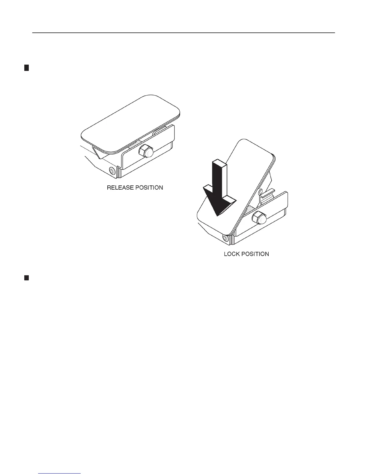
1. Push the front side of swivel lock downwards by foot as shown in ILLUSTRATION 8–92.
SWIVEL LOCK
ILLUSTRATION 8–92
2. Move the LOGIQ 400 console. When the lock lever on the front caster faces just forwards, the swivel mecha-
nism is locked.
3. Try to roll the LOGIQ 400 console and check that the left-side front caster does not rotate.
4. Push the back side of swivel lock down by foot.
5. Try to roll the LOGIQ 400 console again and check that the swivel lock mechanism is released.
8–8–8 Final Procedures
1. Properly dispose of excess material.
2. This completes the installation of the optional Swivel Lock for LOGIQ 400.

 Loading...


