GE MEDICAL SYSTEMS
2127661
LOGIQ 400 SERVICE MANUAL
TM
8–48 OPTIONS
REV 5
8–4–9 Operational Check–out
1. Plug in the system and power the system ON.
2. Power the B/W Video Printer ON.
3. Press New Patient key when the PATIENT ENTRY MENU is displayed on the CRT monitor screen of
LOGIQ 400.
4. Set the system so that the B/W Video Printer can work by the key operation on the console.
The following steps (step a. to m.) indicates one example when you set the B/W Video Printer control with the
conditions below:
I. Connect Mini Plug cable with Plug 1 “B/W Printer” located at front panel of LOGIQ 400. Refer to
ILLUSTRATION 8–51.
II. Set that pressing Record1 key causes the B/W video printer to print image including only B/W
data. (Image including color data is printed by color video printer.)
III. Select B/W printer for printing report page.
IV. Select inverse print for printing report page.
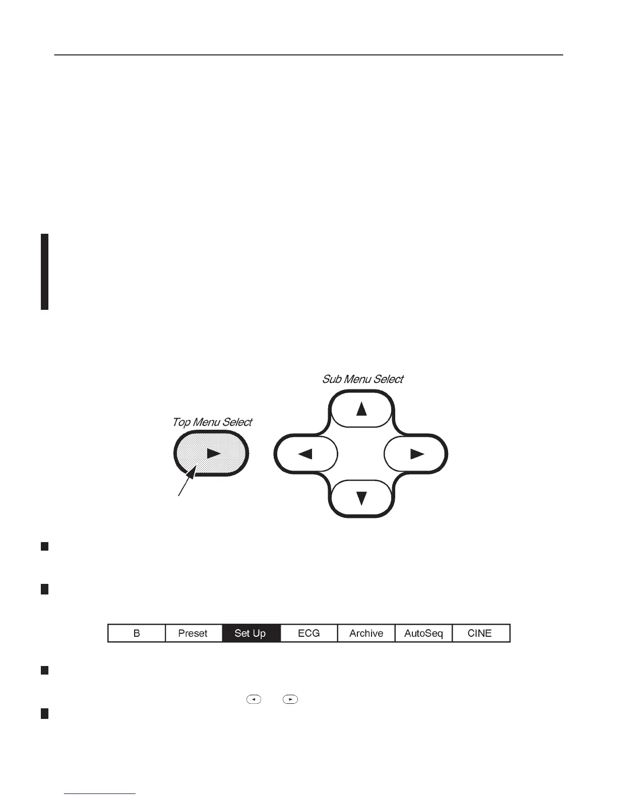
a. Press the Top Menu Select key located on the keyboard. The sub–menu selected previously is displayed on
the CRT monitor screen.
SOFTWARE MENU CONTROL KEYS
ILLUSTRATION 8–52
b. Press the Top Menu Select key again. The top menu is displayed on CRT monitor screen as shown in
ILLUSTRATION 8–53.
TOP MENU
ILLUSTRATION 8–53
c. Select the Set Up Menu using the or key of Sub Menu Select keys. The Set Up selection is dis-
played in reverse video as shown in ILLUSTRATION 8–53.

 Loading...


