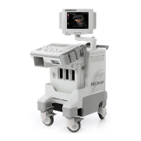
GE MEDICAL SYSTEMS LOGIQ 400 SERVICE MANUAL
2127661
RENEWAL PARTS
6–114
REV 9
6–2–26 Neck Assy (FRU No. 201 for Color Monitor, No. 202 for B/W Monitor)
Time Required
30 Minutes
Tool Required
Screwdriver
Hex Wrench
Procedure
WARNING!
PERSONAL INJURY HAZARD. THE NECK ASSY IS SPRING LOADED. RELEASING ARM
WHEN MONITOR IS NOT INSTALLED WILL CAUSE SUDDEN UPWARD MOVEMENT. KEEP
YOUR HEAD AND BODY AWAY FROM ABOVE NECK ASSY.
Refer to ILLUSTRATION 6–47 on page 6–115.
1. Turn OFF the system and unplug the unit.
2. Push down the Up/Down Release Button located on the Neck Assy, lift the monitor up and set the monitor to the
highest position.
3. Remove the Monitor Assy (FRU No. 100), Monitor Assy NTSC (FRU No. 150) or Monitor Assy PAL (FRU No.
151). Refer to 6–2–1 on page 6–70 or 6–2–12 on page 6–90.
4. Remove the Neck Space Plate.
5. Remove the Front Base Cover (FRU 305). Refer to 6–2–35 on page 6–131.
6. Remove the Side Cover Right (FRU 302). Refer to 6–2–32 on page 6–128.
Note
The Linear Slide Cover is installed from the production unit of LOGIQ400 console with software Ver-
sion 5.01y or later. Refer to ILLUSTRATION 6–48 on page 6–116. Unscrew six screws (
17
–
22
) to
remove the Linear Slide Cover.
7. Remove the Side Cover Left (FRU 301). Refer to 6–2–31 on page 6–127.
8. Remove the Rear Cover (FRU 303). Refer to 6–2–33 on page 6–129.
9. Remove the Top Cover (FRU 308). Refer to 6–2–38 on page 6–135.
10. Remove the Rear CONN Panel Assy (FRU 501). Refer to 6–2–61 on page 6–166.

 Loading...