EasyManuals Logo
Home>GE>Medical Equipment>LOGIQ 400

GE LOGIQ 400 Service Manual

GE LOGIQ 400
526 pages
To Next Page IconTo Next Page
To Previous Page IconTo Previous Page
Page #300 background imageLoading...
Page #300 background image
GE MEDICAL SYSTEMS
2127661
LOGIQ 400 SERVICE MANUAL
RENEWAL PARTS
6–170
REV 9
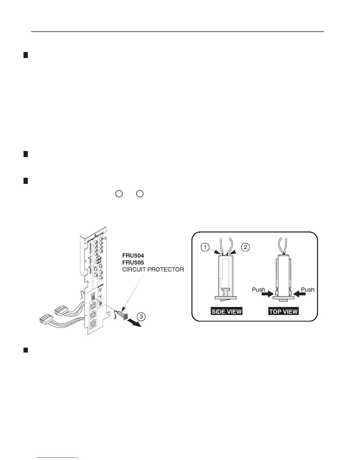
6–2–64 Circuit Protector (FRU No. 504: 15A, FRU No. 505: 7.5A)
Time Required
1 Hour
Tool Required
Screwdriver
Soldering Iron
Procedure
Refer to ILLUSTRATION 6–88.
1. Turn OFF the system.
2. Remove the Rear CONN Panel Assy (FRU 501). Refer to 6–2–61 on page 6–166.
3. Remove the soldered cord (
1
and
2
).
4. Remove the Circuit Protector toward the direction indicated by the arrow.
CIRCUIT PROTECTOR DISASSEMBLY
ILLUSTRATION 6–88

Table of Contents

Other manuals for GE LOGIQ 400

Questions and Answers:

Question and Answer IconNeed help?

Do you have a question about the GE LOGIQ 400 and is the answer not in the manual?

GE LOGIQ 400 Specifications

General IconGeneral
BrandGE
ModelLOGIQ 400
CategoryMedical Equipment
LanguageEnglish

Related product manuals