GE MEDICAL SYSTEMS
2127661
LOGIQ 400 SERVICE MANUAL
SYSTEM CONFIGURATION
3–7
REV 9
3–5 OPTIONAL PERIPHERALS
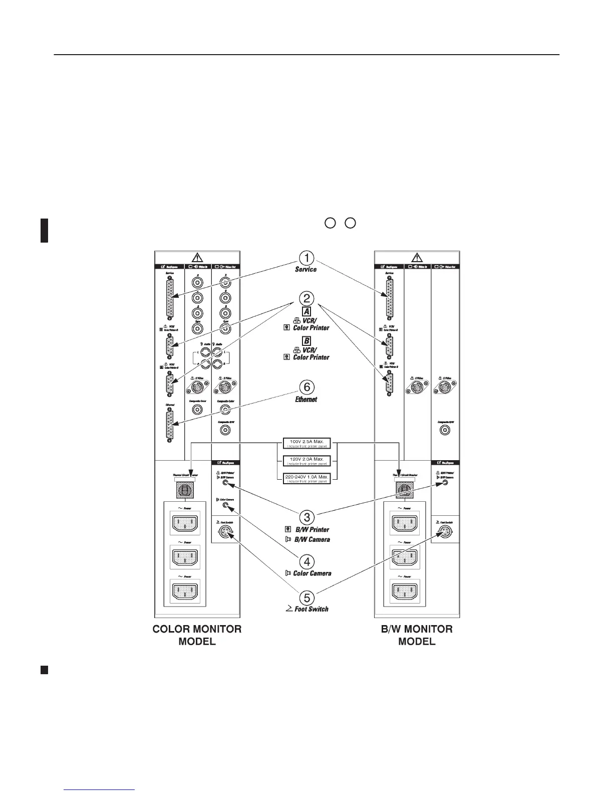
3–5–1 Peripherals/Accessories Connector Panel
LOGIQ 400 peripherals and accessories can be properly connected using the rear connector panel located behind
the rear door.
The serial ports for controlling recording devices, video input/output connectors, audio input/output connectors, cam-
era expose connectors, foot switch connector, and power outlet connectors for peripherals are located on the rear
panel.
This section indicates the pin assignment for each connector (
1
–
6
in ILLUSTRATION 3–4) at pages 3–7 through
3–8.
REAR CONNECTOR PANEL
ILLUSTRATION 3–4
Note
The B/W console with the software version 4.01 or later has the same Rear Connector Panel,

 Loading...


