GE MEDICAL SYSTEMS
2127661
LOGIQ 400 SERVICE MANUAL
RENEWAL PARTS
6–174
REV 9
6–2–67 Nest Fan Assy (FRU No. 511)
Time Required
20 Minutes
Tool Required
Screwdriver
Procedure
Refer to ILLUSTRATION 6–93.
1. Turn OFF the system.
2. Remove the Side Cover Left (FRU 301). Refer to 6–2–31 on page 6–127.
3. Disconnect two connectors (
1
and
2
).
4. Unscrew two screws (
3
and
4
).
5. Pull out the Nest Fan Assy leftwards.
NOTE
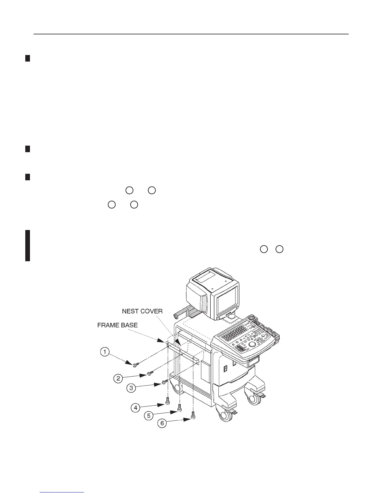
The FRAME BASE is installed from the production unit of the LOGIQ400 console with software ver-
sion 5.01 y or later. Refer to ILLUSTRATION 6–92. Unscrew six screws (
1
– 6 ) to remove the
FRAME BASE.
NEST FAN ASSY DISASSEMBLY(a)
ILLUSTRATION 6–92

 Loading...


