GE MEDICAL SYSTEMS
2127661
LOGIQ 400 SERVICE MANUAL
RENEWAL PARTS
6–166
REV 9
6–2–61 Rear CONN Panel Assy (FRU No. 501)
Time Required
20 Minutes
Tool Required
Screwdriver
Procedure
Refer to ILLUSTRATION 6–85 on page 6–167.
1. Turn OFF the system.
2. Remove the Rear Door Assy (FRU 304). Refer to 6–2–34 on page 6–130.
3. Remove the Rear Cover Assy (FRU 303). Refer to 6–2–33 on page 6–129.
Note
The Linear Slide Cover is installed from the production unit of LOGIQ400 console with software Ver-
sion 5.01y or later. Refer to ILLUSTRATION 6–48 on page 6–116. Remove the Linear Slide Cover.
Note
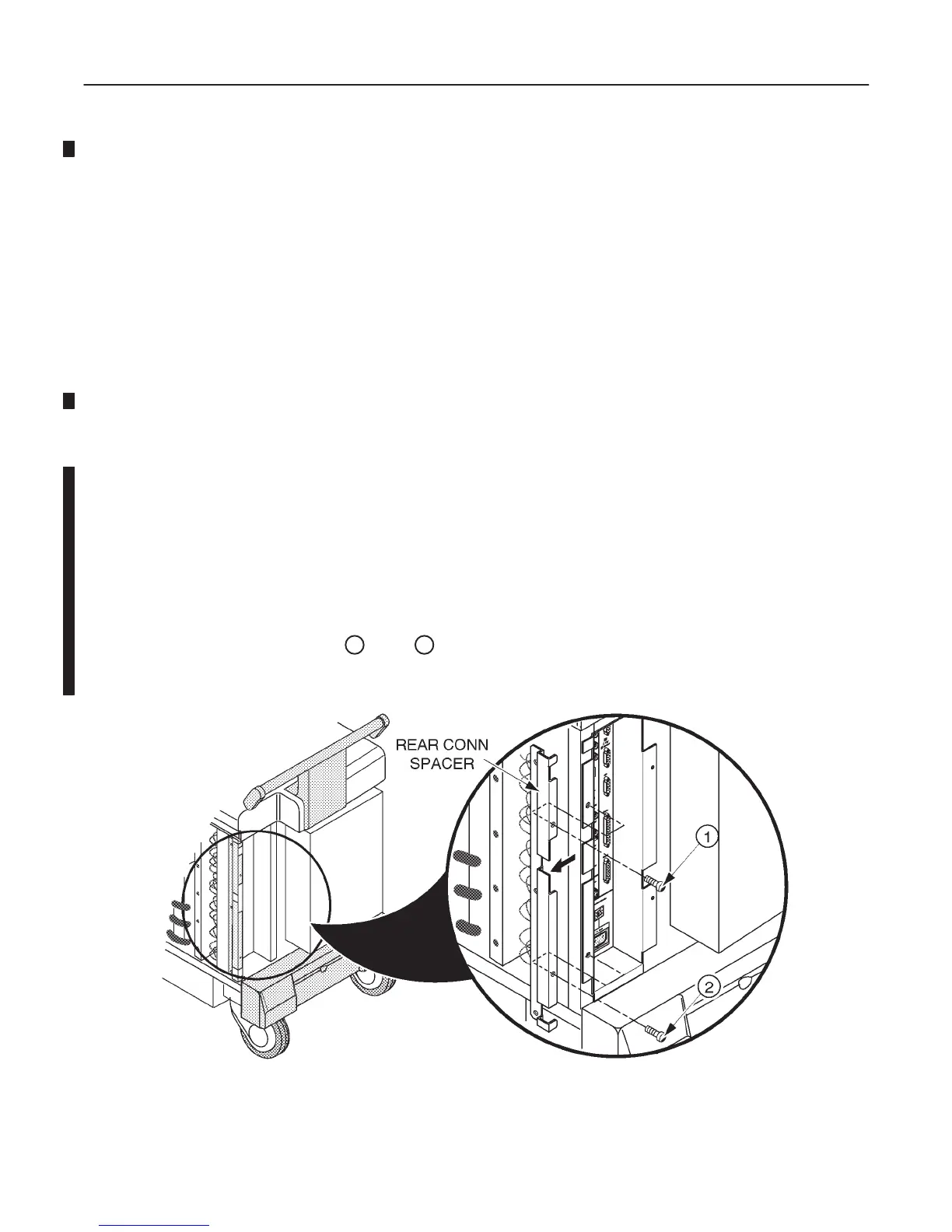
Unscrew the two screws (
1
and
2
) to remove the Rear CONN Spacer. Refer to
ILLUSTRATION 6–84. The Rear CONN Spacer is installed from the production unit of LOGIQ400
console with software Version 5.01y or later.
REAR CONN SPACER DISASSEMBLY
ILLUSTRATION 6–84

 Loading...


