LOGIQ 400 SERVICE MANUALGE MEDICAL SYSTEMS
2127661
RENEWAL PARTS
6–135
REV 9
6–2–38 Top Cover (FRU No. 308)
Time Required
30 Minutes
Tool Required
Screwdriver
Procedure
Refer to ILLUSTRATION 6–61.
1. Turn OFF the system.
2. Remove the Top Cover Sheet.
3. Remove the Side Cover Left (FRU 301). Refer to 6–2–31 on page 6–127.
4. Remove the Side Cover Right (FRU 302). Refer to 6–2–32 on page 6–128.
5. Remove the Rear Cover Assy (FRU 303). Refer to 6–2–33 on page 6–129.
6. Pull the Cable Arm Assy out. Refer to 6–2–45 on page 6–142.
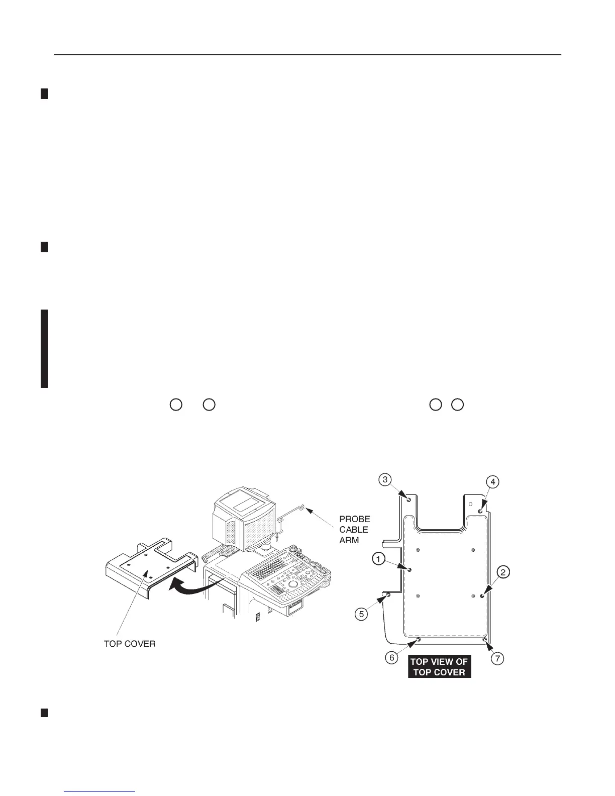
7. Unscrew two screws (
1
and
2
) from the upper side of top cover and five screws (
3
–
7
) from the lower side of
top cover.
8. Remove the Top Cover.
TOP COVER DISASSEMBLY
ILLUSTRATION 6–61

 Loading...


