GE MEDICAL SYSTEMS
2127661
LOGIQ 400 SERVICE MANUAL
7–8 PERIODIC MAINTENANCE
REV 5
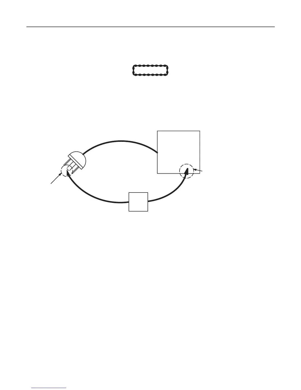
7–3–2 Grounding Continuity
CAUTION
Electric Shock Hazard. The patient must not be contacted to the equipment during this test.
Measure the resistance from the third pin of the attachment plug to the exposed metal parts of the case
(ILLUSTRATION 7–4). The ground wire resistance should be less than 0.2 ohms.
CONSOLE
OHMMETER
GROUND PIN
ACCESSIBLE METAL PARTS
1. Monitor Housing
2. Rear Panel Connector
3. Any Caster/Wheel Support
GROUND CONTINUITY TEST
ILLUSTRATION 7–4
Meter Procedure
Follow these steps to test the ground wire resistance.
1. Turn the LOGIQ 400 unit OFF.
2. Plug the unit into the meter, and the meter into the tested AC wall outlet (Refer to ILLUSTRATION 7–6).
3. Plug the black chassis cable into the meter’s “CHASSIS” connector and attach the black chassis cable clamp to
an exposed metal part of the LOGIQ 400 unit (Refer to ILLUSTRATION 7–6).
4. Set the meter’s “FUNCTION” switch to the RESISTANCE position.
5. Set the meter’s “POLARITY” switch to the OFF (center) position.
6. Measure the ground wire resistance and keep a record of the results with other hard copies of PM data kept on
site.

 Loading...


