LOGIQ 400 SERVICE MANUALGE MEDICAL SYSTEMS
2127661
INSTALLATION
2–13
REV 0
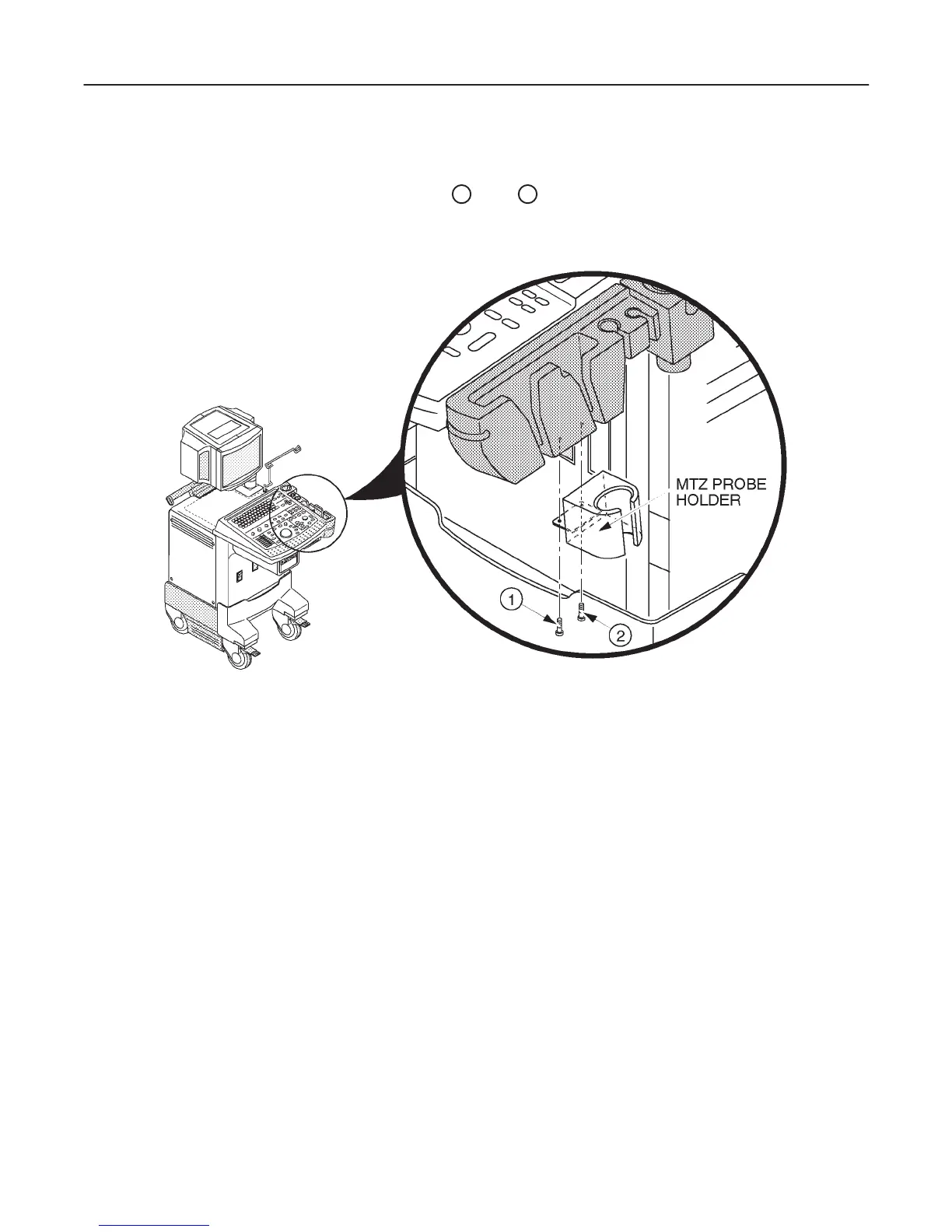
2–2–7 MTZ Probe Holder Installation
One MTZ probe holder is supplied with the LOGIQ 400 console. Assemble the MTZ probe holder at the bottom of
standard probe holder by screwing two screws (
1
and
2
: supplied with the starter kit) as shown in
ILLUSTRATION 2–5.
MTZ PROBE HOLDER INSTALLATION
ILLUSTRATION 2–5
2–2–8 Transducer Connection
Connect a transducer to the upper transducer receptacle as follows:
1. Ensure that the transducer twist lock lever points towards the 3 o’clock position.
2. Insert the transducer connector on the receptacle guide pin until it touches the receptacle mating surface.
3. Twist the transducer twist lock lever to the 7 o’clock position to lock it in place. Twist the lever to the 3 o’clock
position to disconnect the transducer.
Note
It is not necessary to turn the system power OFF to connect or disconnect a transducer.

 Loading...


