www.trilithic.com
Page IV-82
180 DSP Operation Manual
Signal Level Meter
Tilt Measurement & Marker Adjustment
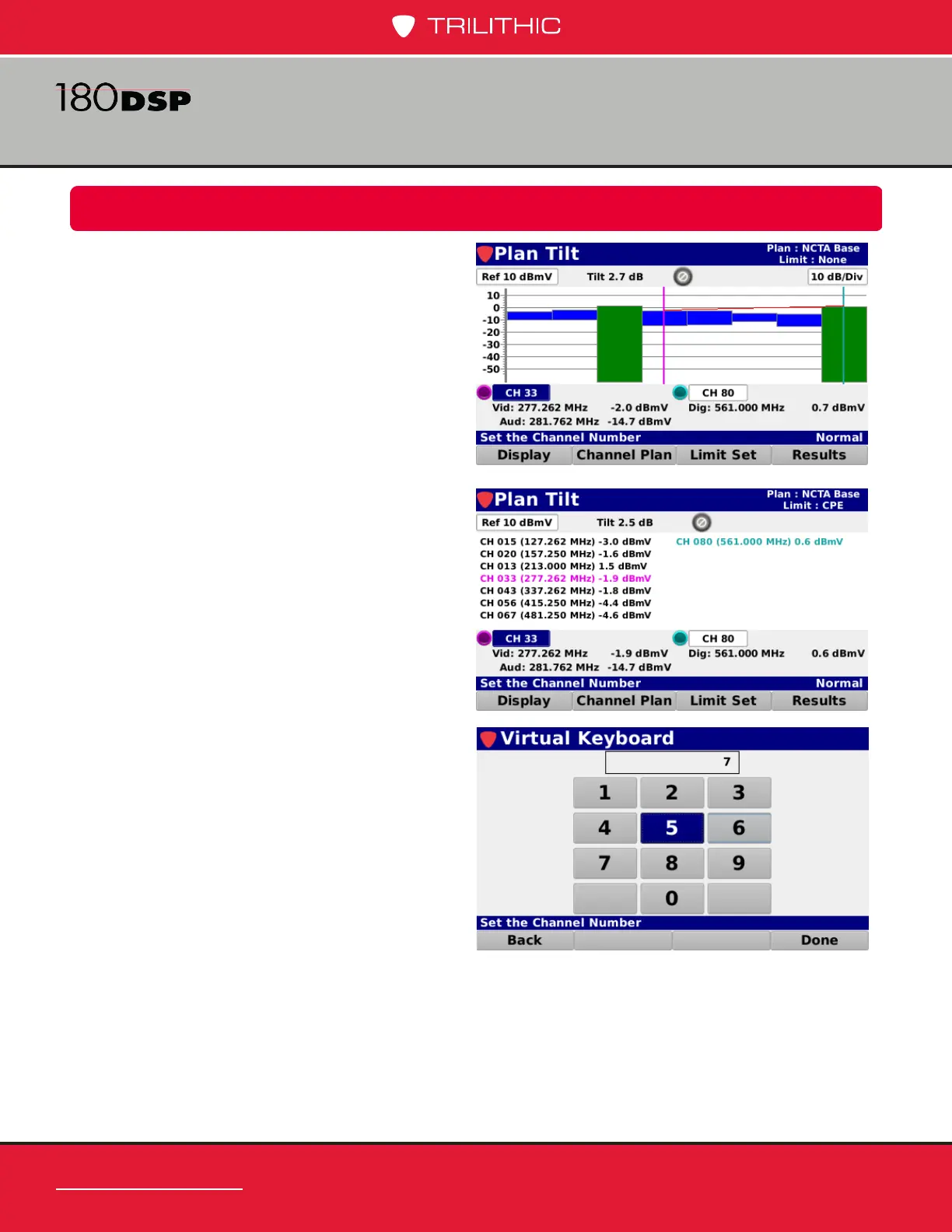
The Plan Tilt screen includes two on-screen
markers that are used for measurement of Tilt
in the channel plan. The Tilt between the two
markers is displayed at the top middle of the
screen as shown in the image to the right.
The markers are represented by the following
color bullets, vertical lines, and text:
• Marker 1 – Purple
• Marker 2 – Light Blue
Highlight the desired marker and use either of
the following methods to change the marker
location:
• Use the up/down arrow buttons to
change the marker for the selected
favorite channel
• Press the Enter button and use the
Virtual Keyboard to directly enter
the channel number as shown in the
image below.
The following information is displayed for
each channel type:
• Analog – Channel number/name,
video/audio frequencies, and video/
audio levels.
• Digital – Channel number/name,
digital video frequency, and level.
• Single Carrier – Channel number/
name, center frequency, and level.
 Loading...