www.trilithic.com
Page IV-161
180 DSP Operation Manual
Signal Level Meter
Basic Settings
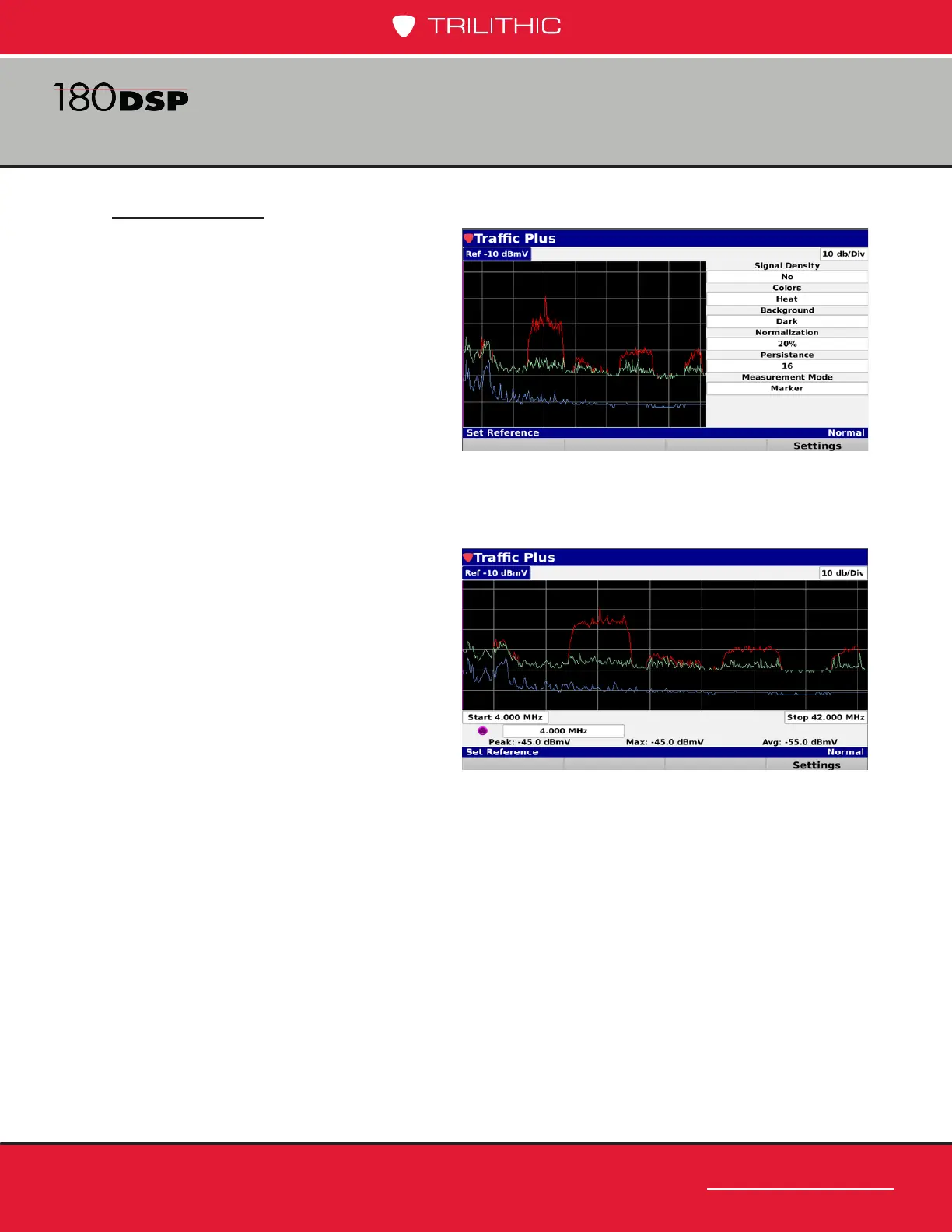
When using the Trafc Control Plus
feature for the rst time, select the
Settings softkey and use the following
conguration:
Signal Density: No
Colors: (Any)
Background: Dark
Normalization: 20%
Persistence: 16
Measurement Mode: Marker
To adjust a setting, highlight the eld, then use the up/down arrow buttons to change.
Once nished, select the Back button and the screen will be displayed as shown in the
image to the right:
The following traces are always shown
on the display.
Red Trace – Max peak signal.
Typically shows an outline of the
existing upstream modem carriers.
Green Trace – Max constant signal,
which may be the noise oor for
a bursty signal or some sort of
continuous signal.
Blue Trace – Average constant signal. Like the green trace, shows the noise oor,
ingress under the carrier, or other unwanted signals.
 Loading...