www.trilithic.com
Page IV-163
180 DSP Operation Manual
Signal Level Meter
Other Settings
The Background setting of the display can be either Dark or Light. Adjust this for the best
readability of the display.
The Persistence setting can be a value from 1 to 32, selectable in multiples of two
(1,2,4,8,16,32). This value has a direct effect on the number of samples used to build the
specic traces. The end effect of this setting is the higher the value, the longer the max
trace stays visible. A suggested value for this eld is 8 or 16.
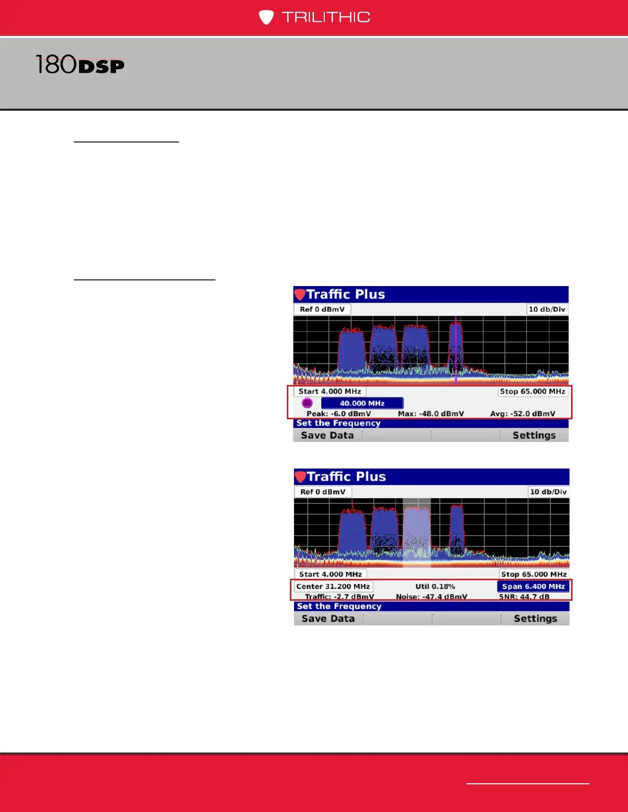
Measurement Mode
The Trafc Control Plus spectrum
has two measurement modes:
Marker mode and Region of
Interest mode. The marker mode
allows the user to move a marker to
any frequency and display the values
of the three traces at that frequency,
as shown in the image to the right.
In the region of interest measurement
mode, you can dene a center
frequency and a span, such as a
cable modem channel. The trafc
level, signal to noise ratio, and
channel utilization will be calculated
for that region. Please note that the
region of interest measurements are
only valid for bursty signals.
 Loading...