10-8 CIC Pro™ 2026419-033E
Preventive maintenance
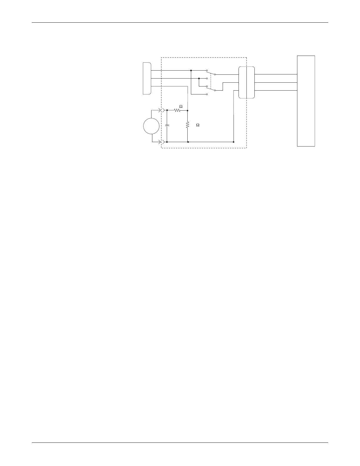
1. Configure the leakage tester like the circuit shown below.
2. Connect the power cord of the device under test to the power receptacle on the
leakage tester.
3. The device under test is to be tested at its normal operating voltage.
4. Set the power switch of the device under test to ON.
5. Read the current leakage indicated on DMM.
6. Set the polarity switch on the leakage tester to RVS (reverse).
7. Read the current leakage indicated on DMM.
NOTE
If either reading is greater than the appropriate specification below, the
device under test fails. Contact GE Technical Support.
300 µA (0.3 volts on the DMM), and the device under test is powered from
100-120 V/50-60 Hz
300 µA (0.3 volts on the DMM), and the device under test is powered from a
centered-tapped 200-240 V/50-60 Hz, single-phase circuit
500 µA (0.5 volts on the DMM), and the device under test is powered from a
non-center-tapped, 200-240 V/50-60 Hz, single-phase circuit
NOTE
Center-tapped and non-center-tapped supply circuits produce different
leakage currents and the UL and IEC limits are different.
8. Set the power switch of the device under test to OFF.
Enclosure leakage current test
Perform this test to measure current leakage through exposed conductive surfaces on
the device under test during normal operation.
Power Cord
Leakage Tester
NORM
RVS
HIGH
LOW
GND
0.015µF
Power Cord
Device
Under
Test
DMM set to measure AC voltage
GND
DMM
10K
1K

 Loading...