11 – 124 HEIDENHAIN Service Manual iTNC 530 HSCI
11.4.2 The LOGIC diagram
With the LOGIC DIAGRAM function you can display the course of the dynamic changes of
PLC operands (M/I/O/T/C).
Activation You are on the PLC main page.
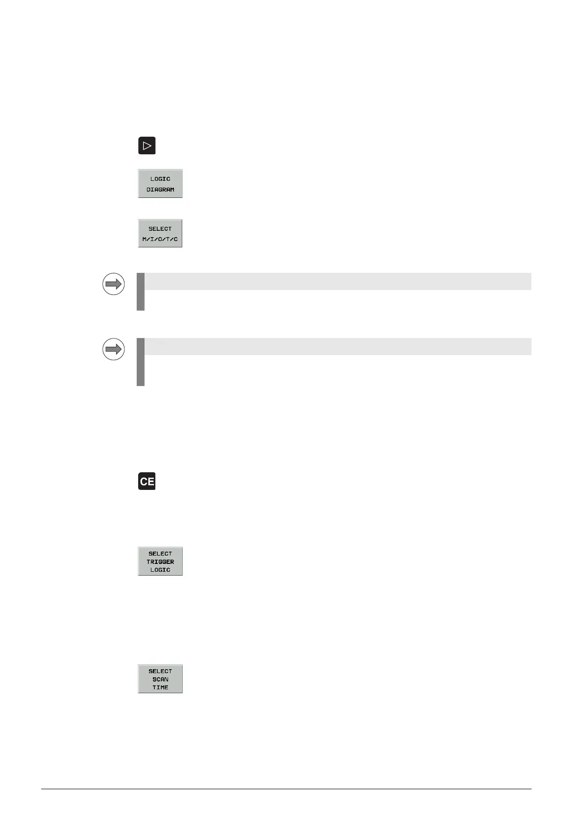
8 Switch to the next soft-key row.
8 Soft key to call the LOGIC DIAGRAM function.
Selecting the
operands
8 Open the selection table.
8 Enter the desired operands.
Defining the
trigger conditions
8 Define the trigger conditions.
The following trigger conditions are defined:
Defining the
trigger logic
8 Define the trigger logic.
Two possibilities are available:
Selecting the
recording time
8 Select a recording time.
Here you specify how long the signal states are recorded from the defined trigger time point.
Four different times are available, depending on the PLC cycle time.
2048 PLC cycles are recorded.
Up to 16 operands can be selected from the table being shown.
If you work with the WATCH LIST , you can also use the ADD TO LOGIC DIAGRAM soft key to add
operands to the logic diagram.
1 Record if operand is logically 1 (trigger on positive edge)
0 Record if operand is logically 0 (trigger on negative edge)
No trigger
OR Recording starts as soon as one of the defined trigger conditions is fulfilled.
AND Recording starts when all of the defined trigger conditions are fulfilled.

 Loading...


